
Resonances Characteristics of Parallel Plate Waveguide Cavities
2015-11-18 10:11:38LinChenDanNiWangYiMingZhuandYanPeng
Lin Chen, Dan-Ni Wang, Yi-Ming Zhu, and Yan Peng
Resonances Characteristics of Parallel Plate Waveguide Cavities
Lin Chen, Dan-Ni Wang, Yi-Ming Zhu, and Yan Peng
—The influence of air gaps on the response of transmission for a transverse-electric mode parallel-plate waveguide (TE-PPWG) with a single cavity and double cavities has been studied experimentally. As the air gap is larger than the resonant wavelength of high order cavity mode in the single deep grooved waveguide, only the fundamental cavity mode can be excited and single resonance can be observed in the transmission spectrum. Based on above observations, a tunable multiband terahertz (THz)notch filter has been proposed and the variation of air gap has turned out to be an effective method to select the band number. Experimental data and simulated results verify this band number tunability. This mechanical control mechanism for electromagnetic induced transparency (EIT) will open a door to design the tunable THz devices.
Index Terms—Electromagnetic induced transparency,metal parallel plate waveguide, terahertz filter.
1. Introduction
The parallel-plate waveguide (PPWG) is a simple structure in the THz range which is well understood in classical waveguide theory and is widely employed due to its low loss and low dispersion characteristics[1]. Owing to the fact that waveguides have the ability to confine radiation, they can be employed in conjunction with resonant structures, resulting in unique spectral resonant features, which opens up PPWG to a myriad of sensing and filtering applications. There have been several designs that employed resonant structures embedded within PPWGs such as Bragg gratings, photonic band gap, and resonant groove(s) structures[2]-[10]. Recently, a single rectangular cavity incorporated into a transverse-electric mode PPWG(TE-PPWG) has been demonstrated as a notch filter with a very narrow line width[11]. The PPWG with a single cavity has also been found to be a strong and high Q resonant system in which the electromagnetic induced transparency(EIT) phenomenon will appear. Astley et al. has characterized the single cavity waveguide resonant structure and also analyzed the origin of the resonant behavior and its dependence on geometric factors[12]. As the groove grows deeper (i.e. depth increases), this dip shifts to lower frequencies. However, there are still some key aspects of the single grooved TE-PPWG performance that has not been sufficiently studied. It should be noted that the grooved PPWG structures are analogous to plasmonic stub metal-insulator-metal (MIM) structures in the visible region[13]-[16]. The stub structure also plays an important role in filtering proposals but lacks the experimental support. Then we reported an observation of an EIT-like phenomenon in THz PPWG double cavities systems and analyzed the relation between the off-position of the cavities and the transmission properties. We also found that two detuned resonances could be varied by choosing different shifting length between double cavities. This means that the phase shift of the propagating wave between two resonances may be another important factor for the realization of EIT. The proposed system has the following features: First, since the most popular metals are seen as perfect conductors due to their extremely large conductivity in the THz region, the realization of THz EIT-like response in PPWG-cavities systems is not plasmonically induced. Second, the double cavities have identical geometry,therefore, the detuning of resonant frequencies does not arise from the different geometrical parameters of two cavities. We also found the EIT-like transmission presented here resulted from the resonances hybridization induced by the change of coupling strength of the top and bottom cavities[17].
The PPWGG is a potentiial EIT devicee. This realization haas encouragedd a continuouss research formimicking EIT in cllassical systemms. In the fieeld of optics,waveguide bbased EEIT-like resonnances havebeen proposeed numericallly in reesonant cavityy systems. Immportantly, thhe phase couppling beetween the reesonators hasbeen provedto be a key ffactor foor EIT-like reesponse[18],[19]]. This papermainly discuusses thhe resonancess characteristiccs of parallelplate waveguuides wwith a single caavity and doubble cavities.
2. PP PWG witt h Single Cavity
A PPWG ssystem with aa single deep ccavity is showwn in Fig. 1 (a), thecavity geomeetry is designeed with a widdth of ww and a depthof h2(when hh1=0 μm, L=00 μm), d represents thhe waveguidee spacing bbetween thetwo plates.The fuundamental TTE mode wasexcited at thee beginning oof the wwaveguide annd the transmmission wasdefined asthe trransmitted powwer through PPPWG cavityy structure divvided byy the transmittted power thrrough PPWGwithout the cavity sttructure. We uused a groovee with a fixedd width of w==400 μmm based on aa previous expperiment[8],[20],, and set the ddepth too be h2=1400μm as our deffault number.For the excittation off TE mode,the incidentTHz wavewas appliedwith poolarization paarallelly to tthe plates[8],[220]. The photto of PPWG with a ssingle deep caavity is shownn in Fig. 1 (b). It is foormed by mmicro-machininng a rectanggular grooveinto boottom plates oof PPWG, resppectively. Eacch plate is madde of poolished nickell-plating Cu.In the experimment, we usedd the teerahertz timedomain specttroscopy (THHz-TDS) systeem to obbtain the outtput power sppectra of PPWG with adeep caavity[8],[10]. Moost of these deevices were mmeasured by ahigh peerformance TTHz-TDS[21]-[225], which isalso made byy the UUniversity ofShanghai forr Science annd Technologyy, as shhown in Fig.1 (c). In thissystem, we uused a P-I-N ddiode ass the terahertzz emitter, whoose frequencycan reach 4.22 THz annd the scan sppeed reaches 110 scan/s.
Fig. 2 showws the measuured time dommain waveformms of frree space andthe groovedPPWG withh1=0 μm, h2=1400 μmm, and d=555 μm, respectively. The eexperimental ssetup haas the frequenncy resolutionn of 4.58 GHzz correspondinng to thhe time domaiin waveformsof ~218.4 ps.
Fig. 3 showws the normaliized power traansmission sppectra foor the waveguuide of three tyypical plate sppacing with adeep grroove incorpoorated. The sppectra showthe characteriistics siingle, double,, and triple reesonant featurres for d=8000 μm,710 μm, and 5555 μm, respecttively.
Fig. 4 commpares the powwer transmisssion spectra oof the siingle deep caavity PPWGwith differennt air gaps. Power trransmission sppectra are callculated by ussing the amplitude raatio of the waaveguide withh and without the incorporated caavity. The ressonance dip att the lowest ffrequency (Baand I,arrrow 1) is clear at all air gaaps in the speectra. Its frequuency iss changed from 0.321 THzz to 0.38 THzwhen the airr gap decrreases from880 μmto 510 μmm, respectively. Interrestingly, theresonance dipp at high frequuency (BandII,arrow 2) in the sppectrum exists explicitly att certain air gap fromm 510 μm to 760 μm. The reesonance dip ((Band III, arroow 3) can be observaable at the airgaps of 670 μμm, 620 μm, 585 μm,555 μm, annd 510 μm,respectively.The dramattic decrrease for the thhree bands coomes from thee increasing looss induuced by moree abrupt junctions betweenthe waveguide sectiions, and thee following smmall change iis owing to tthe highh energy conccentration in thhe deep cavityy. In Fig. 5, tthe twodimensionaltransmissionmap is obtaiined by varyinng inciddent frequency f and air gapp 1/d.
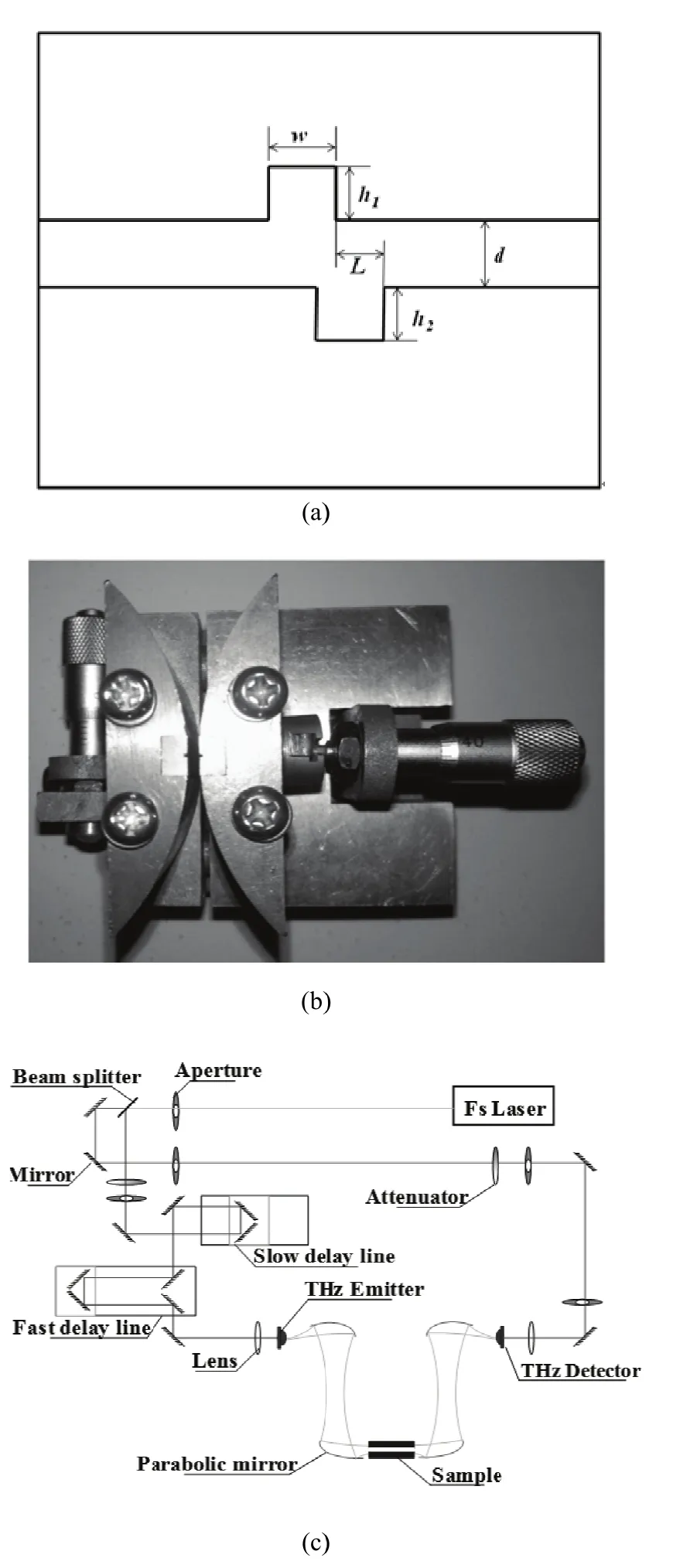
Fig.1. Experimenttal structure annd setup: (a) structure sketchof caviity (cavities) wwaveguide resoonant structure,, (b) schematicof PPWWG sample, andd (c) THz-TDS ssystem.
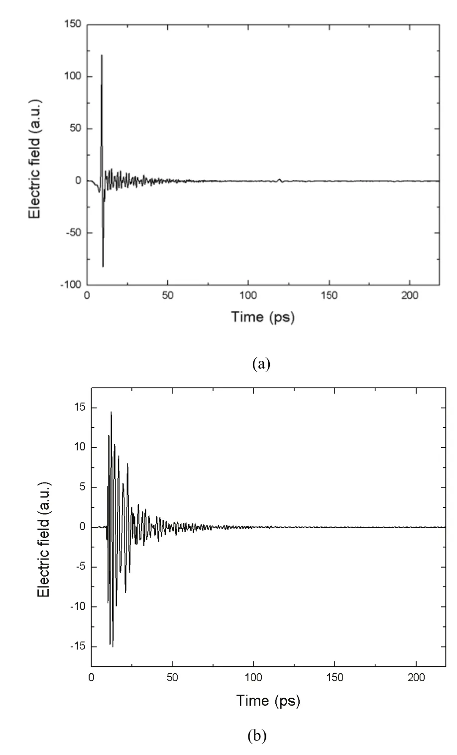
Fiig. 2. Time sscans corresponnding to THzz wave propaggation thhrough: (a) freee space and (b)PPWG with h1=0 μm, h2=1400 μm,annd d=555 μm.

Fiig. 3. Measuured power trransmission sppectra of groooved wwaveguide withh1=0 μm and hh=1400 μm butt varying d.2
Finally, wee make a simpple comparisoon of our propposed sttructure withh some simmilar structurres in theTHz reegion[10],[12]. SSince the singgle groove sttructure insidee the wwaveguide corrresponds tothe resonannt features inn the trransmission sspectra, ourstructure caan operate aas a mmultiband notcch filter byusing the sinngle deep caavity, whicch is very diifferent fromthe single baand notch filtter baseed on one shaallow groovedd TE-mode PPPWG (h1=0 μmm,h2=4412 μm, w=4660 μm) in [122]. Comparedd with the TEEM modde PPWG struucture in [10],, the multiplee resonances aare dueto the excitaation of highh order cavityy modes. Moost impoortantly, for tthe small air ggap, the novell phenomenaof resoonance frequenncy deviationand high ordeer cavity moddes havee been both nnumerically annd experimenttally verifiedin thispaper.
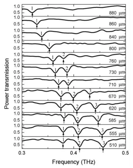
Fig.4. Power trannsmission specttra for differennt air gap d. TThe arrowws indicate shaarp resonancedip (arrow 1: BBand I; arrow2: Bandd II; arrow 3: BBand III).
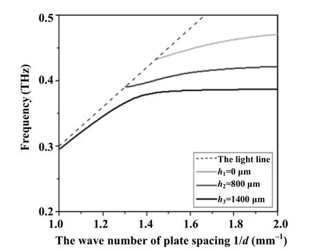
Fig.5. Simulated trransmission maap as a functionn of 1/d with h1=0 μm,h2=800 μm, andd h3=1400 μm.
BBesides, a mmultiband THHz notch fillter with bannd nummber control can be realizedd by tuning thhe air gap. Nootethhat the depthh2(h1=0 μm,L=0 μm) canalso be deepper to exxcite higher oorder cavity mmodes, makingg the deep groooved wwaveguide pootentially a vvery effectivee notch filteer to acchieve much mmore bands coontrol.
3. PPP WG withh Double Cavities
The PPWGG-cavities sysstem introducces the wavegguide sppacing as anoother degreeof freedom.By mechaniically tuuning the wavveguide spaciing between tthe two platess, we exxperimentallyy demonstratethe control off THz waves iin the PPWG-cavitiess system withh the approprriate fixed shiifting leength betweenn the two cavitties that can aachieve EIT.
The PPWGG-cavities sysstem consistsof two alumiinum pllates, each wwith a micro-mmachined recttangular cavitty, as shhown in Fig. 11 (b). All caviities have the iidentical geommetry wwith a widthof w=470 μμm (±5 μm)and a deptth of h1=h2=420 μm(±5 μm). Wee fabricated foour sets of PPPWG caavities configgurations: a pperfect symmeetric one withh the toop and the bottom cavitiees exactly atthe center off the wwaveguide andd asymmetric cconfigurationss made by keeeping thhe top cavityfixed and displacing the bottom cavityfrom thhe center posiition with L=00 μm, 100 μm, 200 μm, andd 300 μmm, respectiveely, where Lrepresents tthe bottom cavity shhifting lengthfrom the cennter in the proopagation direction annd d represennts the lengthof the plates. A combinedd fast annd slow scaan-based THHz time dommain spectrosscopy(TTHz-TDS) wwas used forr evaluatingthe transmisssion prroperties of thhe PPWG sysstem. The fastt optical delayy line wwith a 110 ps rrange can be oobtained. If wwe combine itwith thhe slow scan,, the overalldelay line caan be expandeed to 218.4 ps. Thismeans the eexperimentalspectra resoluution caan reach 4.58GHz. The eleectric field ofthe incident bbeam wwas oriented pparallelly to thhe plates in oorder to excitee the TT E mode.
From the ssimulation off the electricfield distribuution,thhe mode of thhe low frequenncy transmisssion dip shoulld be thhe inverse phaase couplingof the doublee cavities in FFig. 6(aa), and the higgh frequency sshould be thephase couplinng in Fig. 6 (b).
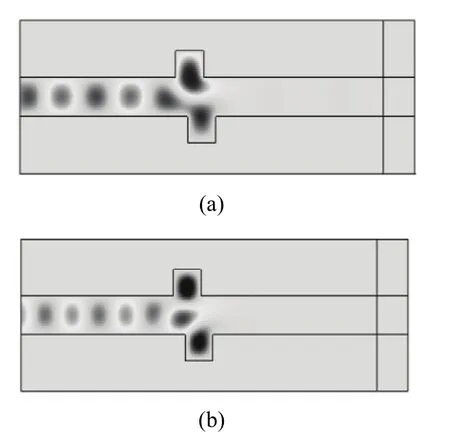
Fiig. 6. Electricfield distribuution of transmmission dip’s ccenter frrequency: (a) loow frequency annd (b) high freqquency.
FFig. 7 showsthe measuredd transmissionn spectra of tthe PPWWG, the PPWGG with a singlle cavity (d=6650 μm) and twwo caviities (d=650 μμm, L=200 μmm), respectiveely. The PPWWG withhout any cavitty acts as thereference. Thhe entire lossis exhiibited in eachh picture of FFig. 8 when thhe frequencyof theincident wavve is lowerthan the cuutoff frequenncy fc=c//2d=0.23 THzz[11],[26]. Forthe single-caavity structurred PPWWG, there wass a resonant frrequency at 0.381 THz. Whhen weadded anotheer cavity on tthe bottom pllate and set tthe staggered lengthL=200 μm, twwo resonant ddips appearedat 0.3554 THz and 00.41 THz, respectively. TThe water-vappor absoorption at 0.5557 THz andd 0.752 THzcould alsobe obseerved in thhis range, wwhich cannoot affect oour expeerimental resuults.

Fig.7. Transmissioon spectra of thee THz wave traansmitted throuugh the PPPWG with sppacing d=650μm, single cavity (w=470 μμm,h=4220 μm), and twoo cavities with tthe shifted lenggth L=200 μm.
NNext, we disccuss the influence of the shhifting lengthh L on thhe transmissioon response. FFor this discusssion, the lenggth of thhe top and boottom plates wwas fixed atd=650 μm. The PPWWG without aany cavity accted as the reeference. Fig.8 showws the powertransmission oof the PPWG--cavities systeem withh different L. FFor the structuure with symmmetry (L=0 μmm),onlyy one broad ssymmetric ressonant dip at0.417 THz wwas obseerved. For thee PPWG cavitties structure wwith L=100 μmm,asymmmetry was inntroduced, ressulting in a neew resonant ddip at alower frequency (0.354 THHz). When the bottom caviity wasfurther shiftted up to L=200 μm, thelower resonaant freqquency showwed blue-shifft and thehigh resonaant freqquency showeed red-shift. AA transparentt band between thetwo resonannt dips becommes narrow aas well as tthe decrrease of thetransmittancee. We observved an EIT-like transmission which was similaar to previous investigatioons for mmeta-materiall and plasmonn analogues oof EIT. For tthe asymmmetric struccture with L=300 μm, tworesonance diips camme closer and tthe transmission peak reducced further. Theexperimental results agree well with the numerical results in Fig. 8 and the deviation is probably caused by the fabrication imperfections of the sample, which introduce further asymmetry and rearrangement of some resonant frequencies. For a complete picture of resonant frequencies change, several calculations were performed with the variation of the shifting length from 0 μm to 450 μm. The detuning |ω1-ω2| (ω1and ω2are low and high resonant frequencies, respectively) decreases and the transparency window narrows down with the increase of the shifting length L.

Fig. 8. Fourier-transformed intensity of the THz wave forms with different L (solid line: simulated, dash line & dots: experimental):(a) L=0 μm, (b) L=100 μm, (c) L=200 μm, and (d) L=300 μm.
This EIT-like transmission can also be explained by analogy to the coupling of bright modes and dark modes. When the bottom cavity is set symmetrically to the top one,only one resonant dip, which corresponds to the two bright modes (each of them has the same resonant frequency), can be excited in both cavities simultaneously. In this condition,the dark modes cannot be excited. When the bottom cavity is shifted backward from the symmetric position, due to the identical geometry of the two cavities, the incident wave first arrives at the top cavity and couples with it. The shifted bottom cavity can hardly be interacted directly with the incident wave any more but can couple with the top cavity. In other words, the top cavity acts as the “radiative”resonator (a bright mode) that is coupled to a “bus”waveguide; the bottom cavity acts as the “sub-radiant”resonator (a quasi-dark mode, induced by the shifting length of two cavities) that cannot be coupled to the “bus”waveguide. This physical picture is similar to the unit cell(consists of an upper gold strip as a bright mode, a pair of lower gold strips as a dark mode, and a dielectric spacer)Then this EIT-like transmission can also be seen as the coupling between bright modes and quasi-dark modes when the symmetry is broken.
Besides, the influence of the length of the top and bottom plates d was also investigated[20]. Four different waveguide spacings with d=610 μm, 670 μm, 740 μm, and 780 μm, were used to study the characteristics of the EIT. Fig. 9 shows the experimental (dots) and simulation (black lines) power transmissions by comparing the spectra of the propagated pulses with and without the cavities. The metal is set as a perfect electrical conductor in the simulation due to the disregard for the attenuation loss of the metal in the THz range. At least three more observations may be inferred by looking at Fig. 9: i) Fig. 9 exhibits a complete loss of spectral power up to the cutoff frequencies of 0.244 THz, 0.236 THz, 0.202 THz, and 0.192 THz, corresponding to d=610 μm, 670 μm, 740 μm, and 780 μm, respectively. ii)The transmission shows strong EIT effect, when d is increased from 610 μm to 780 μm, the low asymmetric resonances shows red-shift. The asymmetric resonant frequencies for d=610 μm, 670 μm, 740 μm, and 780 μm are 0.395 THz, 0.379 THz, 0.354 THz, and 0.338 THz,respectively. This red-shift of high symmetric resonances can also be found for d=610 μm and 670 μm, where the resonant frequencies are 0.456 THz and 0.446 THz,respectively. iii) As d is increased to 740 μm, the main symmetric resonances is degenerated in Fig.9 (c). This effect can also be found when d is equal to 780 μm. The measured and simulated results show good agreements. The deviation of experimental and numerical results is probably caused by the imperfections in the fabrication in real structures, which introduces further rearrangement of resonant frequencies.
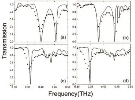
Fig. 9. Measured THz spectra with various air gaps (solid line: simulated, dots: experimental): (a) d=610 μm, (b) d=670 μm, (c)d=740 μm, and (d) d=780 μm.
Firstly, as mentioned above in the experiment, when the waveguide spacing d decreases (1/d increases), the resonant frequencies of both symmetric and asymmetric resonances show red-shift. This red-shift effect is similar to the result of the PPWG with a single cavity for both TE[12]and TM[10]polarizations. The resonant frequency can be expressed as[10]
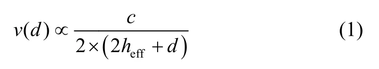
w
where c is thee light velociity in vacuumm (3×10⁸m/ss=0.3 TTHz/mm-1) andd heffis the efffective cavityy height. The vvalue off hefffor the aasymmetric resonances is noot equal to thaat for thhe symmetricc resonancess due to thhe electricfield diifference betwween two resoonances at ressonant frequenncies(sshown in Figss. 4 (b) and (dd) of [17]). Thhis process caauses thhe red-shift off EIT peaks obbserved in booth experimentt and siimulation. The mechanismof red-shift bby the PPWGwith twwo cavities isidentical to tthat of the sinngle cavity[12]], the onnly differencce is thatthe singleFabbri-Palo(FP)reesonance is suupported by PPPWG with one cavity andd two FP resonances are suppoorted by asyymmetric PPPWG caavities.
Accordingto the relationnship betweenn the size d aand λ,thhe dispersiondiagram can bbe divided intto three regionns as inn Fig. 10.
1) RegionI: d<λ/2, themaximum moode order thatt can bee excited is 0.. No stable moode exists.
2) Region III: λ/2<d<λ, thhe maximummode order wwhich caan be excited is 1. Onlyy the lowestt order transvverse ellectric modee TE is exxcited, we ccan observethe trransmission diip in the regioon II.
3) Region IIII: d>λ, the mmaximum moode order is larger thhan 1. The llowest ordertransverse eelectric modeand hiigher transverrse electric moode can be exxcited. Consideering thhe residual effffect of the traansmission dipp, we can obsserve thhe claw type sstructure in reggion III.
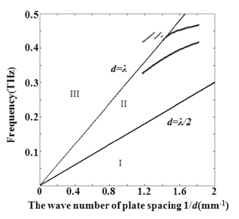
Fiig. 10. Observaation range of PPWG.
So far, wecan describethe mechanismm of manipulation off EIT in a PPPWG cavitiess system. Byfixing approppriate shhifting lengthL (200 μm),as d increasees and the twwo FP reesonant waveelengths are llarger than dd (below thelight line), EIT canbe found obvviously and thhe two resonaances(iincluding thetransparent ppeak) show reed-shift. Oncee the syymmetric FPresonant wavelength is less than d, the TTEM wwave propagattes along a “zzigzag line” aand acts as guuided wavve. The cavvities produce little inflluence on tthe transmission (thatt is, the FP reesonances cannnot exist in tthe regioon above thelight line). Heere the increasse of d converrts theFP resonancees into the gguided wave.Since the EIT transparent peakbetween tworesonances ccomes from tthe desttructive interference of ssymmetric annd asymmetrric resoonances[17], asthe transitionn of symmetricc FP resonancces takee place, this innterference isbroken and aan on-to-off EIT peakk modulationcan be commpleted in thiis process. The mecchanism of above manipulaation is differeent from contrrol of EEIT in meta-material and plaasmonics[27]-[330].
4. Connclusions
In conclusionn, a tunable muultiband terahhertz notch filtter is ppresented expperimentallyand numericcally based oon PPWWG with a ssingle deepcavity and ddouble cavitiees,resppectively. Theadjustable airr gap has beenn investigatedto flexiibly modify thhe filtering chharacteristics oof the presentted filter. The air gaap can also bbe varied in tthe applyingto adjuust the band nnumber. Becauuse the air gaap can be easiily tunaable by mechaanical controlor electrical aadjustment, thhis deepp cavity PPWGG structure haas great potenttial applicatioons in TTHz communiications. Anon-to-off conntrol of the EEIT resoonances is achhieved by mecchanically tuniing the spacinng. It mmay inspire intterest in deveeloping mechaanically tunabble wavveguide basedd EIT, resultinng in a widerange of novvel commpact THz deevices, suchas slow lighht componennts,senssitive sensorrs, and ellectromagnetically induced absoorbers.
Acknowlee dgment
TThis work wa as supported by the Shanghai Rising-Star Prog gram under Gra ant No. 14QA1403100, Proggram of Shanghhai Subj ect Chief Scienntist under Gra ant No. 14XD11403000, Hujia ang Founndation of Chi ina under Grannt No. C14002, Zhejiang KKey Disc cipline of Instru ument Science a and Technology y under Grant NNo. JL1550505, and the New Century Excellent Tale ents Project fro om the MMinistry of Eduucation under GGrant No. NCETT-12-1052.
Referee nces
[1]R. Mendis annd D. Grischkowwsky, “Undistorted guided-waave propagationof subpicoseccond terahertzpulses,” Optiics Letter, vol. 266, no. 11, pp. 8446-848, 2001.
[2]J. M. Nagell, P. H. Boliivar, and H.Kurz, “Moduular parallel-plateTHz componeents for cost-effficient biosensiing systems,” Semmiconductor Sccience and Technology, vol. 220,no. 7, pp. S2881-S285, 2005.
[3]C.-Y. Lin, M. Wu, J. A. Blloom, I. J. Coxx, and M. Milller,“Rotation,scale, andtranslationresilient pubblic watermarkingg for imagess,” IEEE Traans. on Imaage Processing, vol. 10, no. 5, ppp. 767-782, 20001.
[4]J. Kitagawa, MM. Kodama, S.Koya, Y. Nishhifuji, D. Armannd,and Y. Kadoyya, “THz wavepropagation inn two-dimensionnal metallicphootoniccrystalwithmechaanicallytunabblephotonic-bands,” Optics Express, vol. 20, no. 16, pp. 17271-17280, 2012.
[5] R. Mendis, V. Astley, J. Liu, and D. M. Mittleman,“Terahertz microfluidic sensor based on a parallel-plate waveguide resonant cavity,” Applied Physics Letter, vol. 95,no. 17, pp. 171113-1-171113-3, 2009.
[6] E. S. Lee, J.-K. So, G.-S. Park, D. Kim, C.-S. Kee, and T. I. Jeon, “Terahertz band gaps induced by metal grooves inside parallel-plate waveguides,” Optics Express, vol. 20, no. 6,pp. 6116-6123, 2012.
[7] E. S. Lee, S.-G. Lee, C.-S. Kee, and T.-I. Jeon, “Terahertz notch and low-pass filters based on band gaps properties by using metal slits in tapered parallel-plate waveguides,”Optics Express, vol. 19, no. 16, pp. 14852-14859, 2011.
[8] L. Chen, C.-M. Gao, J.-M. Xu, X.-F. Zang, B. Cao, and Y.-M. Zhu, “Observation of electromagnetically induced transparency-like transmission in terahertz asymmetric waveguide-cavities systems,” Optics Letter, vol. 38, no. 9,pp. 1379-1381, 2013.
[9] V. Astley, K. S. Reichel, J. Jones, R. Mendis, and D. M. Mittleman, “Terahertz multichannel microfluidic sensor based on parallel-plate waveguide resonant cavities,”Applied Physics Letter, vol. 100, no. 23, pp. 231108-1-231108-4, 2012.
[10] E. S. Lee and T. Jeon, “Tunable THz notch filter with a single groove inside parallel-plate waveguides,” Optics Express, vol. 20, no. 28, pp. 29605-29612, 2012.
[11] R. Mendis and D. M. Mittleman, “Comparison of the lowest-order transverse-electric (TE) and transverse-magnetic (TEM) modes of the parallel-plate waveguide for terahertz pulse applications,” Optics Express,vol. 17, no. 17, pp. 14839-14850, 2009.
[12] V. Astley, B. McCracken, R. Mendis, and D. M. Mittleman,“Analysis of rectangular resonant cavities in terahertz parallel-plate waveguides,” Optics Letter, vol. 36, no. 8, pp. 1452-1454, 2011.
[13] L. Chen, Z.-Q. Cao, F. Ou, H.-G. Li, Q.-S. Shen, and H.-C. Qiao, “Observation of large positive and negative lateral shifts of a reflected beam from symmetrical metal-cladding waveguides,” Optics Letter, vol. 32, no. 11, pp. 1432-1434,2007.
[14] X.-S. Lin and X.-G. Huang, “Tooth-shaped plasmonic waveguide filters with nanometeric sizes,” Optics Letter, vol. 33, no. 23, pp. 2874-2876, 2008.
[15] M. Yosuke, O. Toshihiro, H. Masanobu, F. Masuo, and N. Masatoshi, “Characteristics of gap plasmon waveguide with stub structures,” Optics Express, vol. 16, no. 12, pp. 16314-16325, 2008.
[16] X. Piao, S. Yu, S. Koo, K. Lee, and N. Park, “Fano-type spectral asymmetry and its control for plasmonic metal-insulator-metal stub structures,” Optics Express, vol. 19, no. 11, pp. 10907-10912, 2011.
[17] L. Chen, C.-M. Gao, J.-M. Xu, X.-F. Zang, B. Cai, and Y.-M. Zhu, “Observation of electromagnetically induced transparency-like transmission in terahertz asymmetric waveguide-cavities systems,” Optics Letter, vol. 38, no. 9,pp. 1379-1381, 2013.
[18] X.-F. Zang, T. Zhou, B. Cai, and Y.-M. Zhu, “Single-photon transport properties in an optical waveguide coupled with a Λ-type three-level atom,” Journal of the Optical Society of American B, vol. 30, no.5, pp. 1135-1140, 2013.
[19] X.-F. Zang, T. Zhou, B. Cai, and Y.-M. Zhu, “Controlling single-photon transport properties in a waveguide coupled with two separated atoms,” Journal of Physics B, vol. 46, no. 14, pp. 145504-1-145504-6, 2013.
[20] L. Chen, J.-M. Xu, C.-M. Gao, X.-F. Zang, B. Cai, and Y.-M. Zhu, “Manipulating terahertz electromagnetic induced transparency through parallel plate waveguide cavities,”Applied Physics Letters, vol. 103, no. 25, pp. 251105-1-251105-4, 2013.
[21] Y.-M. Zhu, T. Unuma, K. Shibata, and K. Hirakawa,“Femtosecond acceleration of electrons under very high electric fields in bulk GaAs investigated by time-domain terahertz spectroscopy,” Applied Physics Letters, vol. 93, no. 4, pp. 042116, 2008.
[22] Y.-M. Zhu, T. Unuma, K. Shibata, and K. Hirakawa, “Power dissipation spectra and terahertz intervalley transfer gain in bulk GaAs under high electric fields,” Applied Physics Letters, vol. 93, no.23, pp. 232102-1-232102-3, 2008.
[23] Y.-M. Zhu, L. Chen, Y. Peng, M.-H. Yuan, Y. Wen, and S.-L. Zhuang, “Temperature dependence of nonequilibrium transport time of electrons in bulk GaAs investigated by time-domain terahertz spectroscopy,” Applied Physics Letters, vol. 99, no. 2, pp. 022111-1-022111-3, 2011.
[24] Y.-M. Zhu and S.-L. Zhuang, “Terahertz electromagnetic waves emit from semiconductor investigated by time domain terahertz spectroscopy,” Chinese Optics Letters, vol. 9, no. 11, pp. 110007, 2011.
[25] J.-M. Xu, L. Chen, L. Xie, S.-Q. Du, M.-H. Yuan, Y. Peng,and Y.-M. Zhu, “Effect of boundary condition and periodical extensionon transmission characteristics of terahertz filterswith periodical hole array structure fabricatedon aluminum slab,” Plasmonics, vol. 8, no. 3, pp. 1293-1297,2013.
[26] R. Mendis, V. Astley, J. Liu, and D. M. Mittleman,“Terahertz microfluidic sensor based on a parallel-plate waveguide resonant cavity,” Applied Physics Letters, vol. 95,no. 17, pp. 171113-1-171113-3, 2009.
[27] Y. Huang, C.-J. Min, and G. Veronis, “Subwavelength slow-light waveguides based on a plasmonic analogue of electromagnetically induced transparency,” Applied Physics Letters, vol. 99, no. 14, pp. 143117-1-143117-3, 2011.
[28] Z.-H. Han and S. I. Bozhevolnyi, “Plasmon-induced transparency with detuned ultracompact Fabry-Perot resonators in integrated plasmonic devices,” Optics Express,vol. 19, no. 4, pp. 3251-3257, 2011.
[29] Z.-Y. Li, Y.-F. Ma, R. Huang, R. J. Singh, J.-Q. Gu, Z. Tian,J.-G. Han, and W.-L. Zhang, “Manipulating the plasmon-induced transparency in terahertz metamaterials,”Optics Express, vol. 19, no. 9, pp. 8912-8919, 2011.
[30] J.-Q. Gu, R. Singh, X.-J. Liu, X.-Q. Zhang, Y.-F. Ma, S. Zhang, S. A. Maier, Z. Tian, A. K. Azad, H.-T. Chen, A. J. Taylor, J.-G. Han, and W.-L. Zhang, “Active control of electromagnetically induced transparency analogue in terahertz metamaterials,” Nature Communications, vol. 3,1151-1-1151-6, 2012.

Lin Chen was born in Jiangsu, China in 1980. He received the B.S. and M.S. degrees from the Southeast University in 2002 and 2005,both in electrical engineering, and the Ph.D. degree from the Shanghai Jiao Tong University in 2008, in optics, respectively. Now he is an associate professor with the University of Shanghai for Science and Technology. His research interests include terahertz waveguide,meta-material, and lab on chip. He has been awarded the “Chen Guang” Scholar in 2009, China Instrument Society-JinGuofan Youth Award in 2011, and Shanghai “rising star” Scholar in 2014. He has published more than 40 SCI papers and 20 patents. As the project leader, he is also responsible for several national funds and funds supported by Shanghai government.

Dan-Ni Wang was born in Anhui, China in 1991. She received her B.S. degree from the Shanghai Normal University in 2013. She won the National Scholarship and Shuikang Feng Scholarship in 2012. She was awarded the outstanding graduates of Shanghai in 2013. Now, she is a postgraduate with the University of Shanghai for Science and Technology. Her research interests include terahertz waveguide, meta-material, and sensor chip.

Yi-Ming Zhu graduated from the University of Tokyo, now he is a professor with the University of Shanghai for Science and Technology, the vice director of the Shanghai Key Lab of Modern Optical System, and the associate dean of the Research Institute of Optoelectronics. He studied at Shanghai Jiaotong University from 1998 to 2002 and received a bachelor degree in apply physics. In 2003, he began to work as an assistant researcher with the Research Center for Advanced Science and Technology, University of Tokyo. He won the Japanese Government Scholarship in 2004 and studied electronics engineering in University of Tokyo as a doctor candidate. He gained his Ph.D. degree in electronics engineering in 2008. He has published more than 100 papers on SCI/EI journals as the first author or corresponding author, including two publication on Nature Group series, more than 20 papers in SCI section II and above, He has also presided more than 20 projects at the national and ministerial/provincial levels, which include one project supported by National 863 Project, 3 projects supported by National Natural Science Foundation of China, 2 sub-projects supported by National 973 Project, 2 projects supported by Major National Development Project of Scientific Instrument and Equipment, etc.

Yan Peng was born in Anhui, China in 1982. She received the B.S. degree from the Anhui Normal University in 2004 and the Ph.D. degree from the East China Normal University in 2009, both in physics. She is an associate professor with the University of Shanghai for Science and Technology. Her research interests include ultrafast optics, terahertz, high-order harmonic generation, and microstructure.
As a project leader, Dr. Peng is responsible for the National Program on Key Basic Research Project of China (973 Program,sub-project), two National Development Projects of Scientific Instrument and Equipment, one National Natural Science Foundation of China, one State Scholarship Fund, and two projects from Shanghai Municipal Education Commission. She was awarded the “Chen Guang” Scholar in 2012, China Instrument Society-Jin Guofan Youth Award, and “Excellent Woman” Award of University of Shanghai for Science and Technology. Up to now, she has published more than 30 SCI papers and 20 patents.
Manuscript received June 5, 2015; revised June 17, 2015. This work was supported by the National Program on Key Basic Research Project of China under Grant No. 2014CB339806, Basic Research Key Project under Grant No. 12JC1407100, Major National Development Project of Scientific Instrument and Equipment under Grant No. 2011YQ150021 and No. 2012YQ14000504, and the National Natural Science Foundation of China under Grant No. 11174207, No. 61138001, No. 61205094, and No. 61307126.
Y.-M. Zhu and Y. Peng are with the Shanghai Key Lab of Modern Optical System, Engineering Research Center of Optical Instrument and System, Ministry of Education, University of Shanghai for Science and Technology, Shanghai 200093, China (Corresponding authors e-mail:ymzhu@usst.edu.cn; py@usst.edu.cn)
L. Chen and D.-N. Wang are with the Shanghai Key Lab of Modern Optical System, Engineering Research Center of Optical Instrument and System, Ministry of Education, University of Shanghai for Science and Technology, Shanghai 200093, China (e-mail: linchen@usst.edu.cn;danniwang07@163.com)
Digital Object Identifier: 10.3969/j.issn.1674-862X.2015.02.007
 Journal of Electronic Science and Technology2015年2期
- Journal of Electronic Science and Technology的其它文章
- QCM Sensors Based on PEI Films for CO2Detection
- Energy-Based Collaborative Spectrum Sensing for Cognitive UWB Impulse Radio
- Monitoring of PON System Using Compound Surveillance Technique
- Design and Realization of an NFC-Driven Smart Home System to Support Intruder Detection and Social Network Integration
- Modeling of a Planar Nine-Way Metamaterial Power Divider/Combiner
- Robust Stability of a Class of Fractional Order Hopfield Neural Networks