
Novel Coil Winding Method to Realize Pot Heated Evenly
2015-11-18 10:11:36MaoYanWangHaiLongLiMengZhangZhiTaoXuCuiLinZhongandJunXu
Mao-Yan Wang, Hai-Long Li, Meng Zhang, Zhi-Tao Xu, Cui-Lin Zhong, and Jun Xu
Novel Coil Winding Method to Realize Pot Heated Evenly
Mao-Yan Wang, Hai-Long Li, Meng Zhang, Zhi-Tao Xu, Cui-Lin Zhong, and Jun Xu
—To solve the problem about the inhomogeneous thermal effect of pot heated by coils along the circumference, a novel coil winding method is proposed and compared with the general winding method in the paper. First, based on the Biot-Savart law and Ampere’s rule, the magnetic induction generated by a straight current carrying conductor and a current loop is discussed, respectively. Then the novel coil winding method is developed by adjusting the location of inhomogeneous joints. The joints are periodically scattered along the circumferential direction and symmetrically designed around the central axis. Numerical results show that the quite non-uniform temperature in the base of pot at the circular direction is effectively improved by using the proposed winding method. The potential danger produced by high temperature at some region of coils plate is minimized. It is energy-efficient and safe for residential appliances.
Index Terms—Coil, inhomogeneous, magnetic induction, thermal, winding method.
1. Introduction
The induction heating technology is widely used in the residential appliances[1]-[2]and industrial fields[3]because of its precise control, low pollution, high efficiency, and safety. The efficiency of an induction heating appliance mostly depends on the power converter and inductor system[2]-[3]. Except the impedance model[4]discussed, the efficiency of the inductor system is hardly concerned. The current-carrying coils of the system generate a low frequency time-varying and close magnetic field that induces numerous small eddy currents on the bottom of the pot. The eddy currents make the pot heat up. The coils are the most important component that affects the production cost and decides the quality of the appliance. The inhomogeneous magnetic field distribution affected by the geometry of coils makes the local high temperature easily occur due to the limitation of the winding process and method. There is no effective technique to thoroughly solve the inhomogeneous heating problem, though the inhomogeneity has been ameliorated by adding ferrite,changing the radii, and winding method of coils, etc. The boiling water function of the induction cooker is hardly influenced by the inhomogeneity. However, it is vital to rice cooker and electric pressure cooker as the rice grains are broken, burned, and half-cooked due to the inhomogeneity, which is insecure and inefficient.
Currently, the common winding methods of coils[4]-[10]are as follows: 1) The coils plate is continuously and tightly wound[4]-[7]. 2) Double rings are spaced and wound in parallel, i.e. the base of the plate is wound by two separate coils that keep a certain distance[5],[8]. 3) The coils are wound from the bottom to the side face of the plate[2]. 4)Multi-rings or two layer coils are wound on the bottom of plate[9], and so on. Compared with the first dense winding mentioned above, the other spaced winding method has the advantages of lower cost and higher winding efficiency. Because the perimeter of coils is far shorter than the working wavelength, the asymmetry of the spaced winding coils along the circumference has been neglected and the coils are considered as an inductance of a high frequency resonant circuit. For simplicity and nice appearance, the inhomogeneous joints connecting the upper and bottom coils at the same loop, and the coils at the adjacent loops are almost in the 20˚ sector region of the plate during the coils machining process[11]. When the coils are computed with simulation software, they are usually replaced by software’s homogeneous current source and not considered as a solid. Though the inhomogeneous heating phenomena of coils have been researched[5], the heating effectsproduced by the intrinsic bug of joints are not studied.
This paper is organized as follows. The theoretical analysis for a straight current carrying conductor and current loop is firstly given, and then the proposed and general coils winding methods are illustrated in Section 2. Moreover, in Section 3, the temperature of pot heated by one wire separately realized with the proposed and general winding methods are compared. Finally, the conclusion is summarized in Section 4.
2. Theoretical Analysis
Except dense winding, spaced winding coils are usually composed of general circular parts and inhomogeneous joints[6],[9],[12]including the upper and bottom coils at the same loop, and coils at the adjacent loops. The magnetic field produced by the current-carrying coil satisfies the Biot-Savart law as discussed below.
The magnetic induction produced by the current element Idl in Fig. 1 (a) can be written as
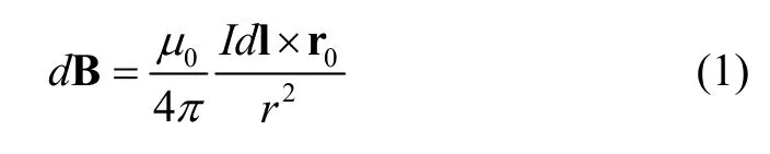
which is called the Biot-Savart law; where dB is the magnetic field of a current element; I is a steady constant current; dl represents the infinite small length of conductor carrying electric current I; r0means the unit vector pointing from the current to the field point; l denotes the length from the current source to the original point O; r is the length from field point to the border of the conductor; a represents the perpendicular distance from the field point to the conductor; μ0=4π×10-7Tm/A is the permeability of vacuum.
Based on the superposition principle, the magnetic induction produced by any current carrying conductor or coil is

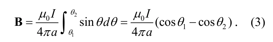
The magnetic induction generated by a straight current carrying conductor shown in Fig. 1 is
Ampere’s rule can be applied to the direction in which the current and magnetic induction are associated as shown in Fig. 1 (b).
According to the Biot-Savart law, the magnetic induction caused by a current loop[13]in a cylindrical coordinate system at the arbitrary point in Fig. 2 (a) can be derived as
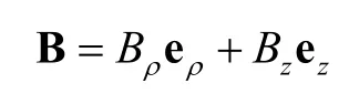
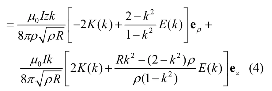
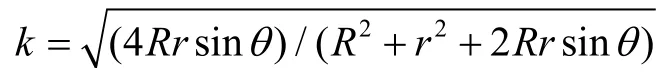

Fig. 1. Magnetic induction produced by current carrying direct wire: (a) amplitude and (b) direction.
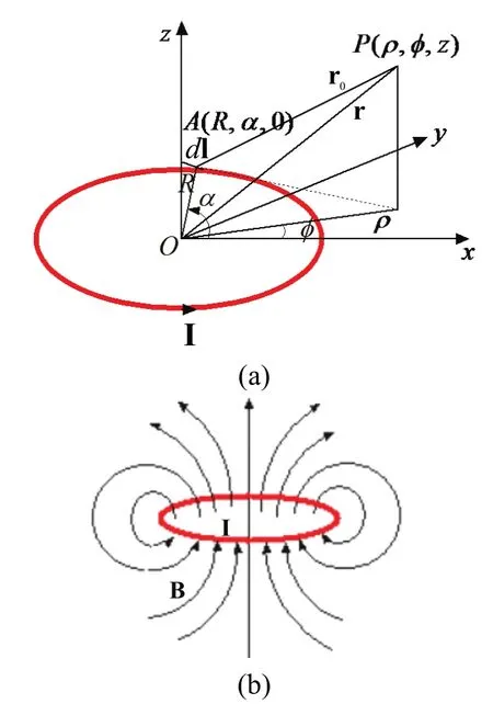
Fig. 2. Magnetic induction produced by current carrying circular coil: (a) amplitude and (b) direction.
The magnetic field distributions for a current carrying joint and a straight conductor are similar, and the magnetic field distributions for the current carrying general circularparts of coils and intact coils are resembled[14],[15]. The magnetic fields for the general circular parts and inhomogeneous joints of the current carrying coils are superposed, i.e. strengthened or counteracted at some region along the circumference. If a pot is surrounded by the alternating magnetic induction, the eddy current will be induced on the surface of the pot based on the Faraday law of electromagnetic induction and the skin effect to make the pot heated[16].
3. Numerical Results
The coil plate is usually wound by dozens of mutually insulated lacquered wires. The lacquered wires can be folded, intercrossed, twisted, and so on. The working frequency of coils is f=25 kHz, i.e. λ=12000 m. The diameter of lacquered wire is 0.33 mm. Because the actual coils made of lacquered wires are electrically small objects,the computer with multi-central processing units and big memory takes a very long time to initialize the mesh as computing the magnetic induction of the coils. To simplify the physical model, only one copper wire is used in the paper to simulate the whole coils. Because the conductivity and thermal conductivity of copper are larger than those of cheaper aluminum, and the thermal efficiency of copper wire is larger than that of the aluminum wire. The copper wire is built with Solidworks software to wind 13 concentric loops. There are one upper and one bottom rings at each loop as shown in Fig. 3. The heating effect for actual coils can be obtained with the superposition principle. The complex and symmetrical characteristic about the center axis should be considered as selecting the number of the joints.
Fig. 3 compares the configuration of the proposed and general coil winding methods. The inhomogeneous joints are scattered evenly along the circumference as shown in Fig. 3 (a), whereas the inhomogeneous joints are in the right 20˚ sector region in Fig. 3 (b). As shown in Fig. 3 (a),the joint links 2-1 connect the upper and bottom rings at each same loop, and the joint links 2-2 connect the upper ring at one loop and the bottom ring at the outer and adjacent loop. The interval angle θ1between the initial and terminal points of each link 2-1 is 20˚, as well as the interval angle θ2between the initial and terminal points of each link 2-2 is 20˚. The interval angles between adjacent links 2-1 and 2-2 are θ2=θ4=10˚. The interval angle for each joint is θ1+θ2+θ3+θ4. There are totally 12 joints in two circumferences.
The inhomogeneous joints have some symmetrical characteristic about the center axis. As shown in Fig. 3 (a),the interval angle of the nth link 2-1 and that of the (n+3)th link 2-1 are symmetrical about the zero point, though the lengths of the links are different. The dash line connecting terminal points of the nth link 2-1 and the (n+3)th link 2-1 is passing through the zero point in Fig. 3 (a). The two links rotate θ1clockwise and counter-clockwise, respectively,and spatially form “X” that relates to the zero point. To some extent, the symmetries counteract the inhomogeneity of the magnetic induction distribution caused by each link.

Fig. 3. Geometry of coil winding methods: (a) proposed and (b)general.
In Fig. 3 (b), the coils regularly wind 360-θ1(θ1=θ2=θ3=θ4) degree angle along these concentric circles. But the upper rings 1-2 in Fig. 3 (a) wind 360-θ1-θ2-θ3degree angle except at the outermost loop, and the bottom rings 1-1 in Fig. 3 (a) wind 360-θ1-θ3-θ4degree angle except at the innermost loop in Fig. 3 (a). The total length of general coil winding method is much longer than that of the proposed coil winding method under the same condition,such as with the identical number of the concentric circles and the same radiuses.
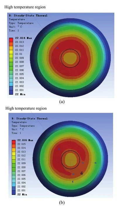
Fig. 4. Temperature distribution on the bottom of a pot: (a)proposed winding method and (b) general winding method.
By using the Comsol Multiphysics Ansys Workbench software integrated with Ansoft Maxwell software, Fig. 4 illustrates the temperature distribution on the bottom of pot heated by the coils realized with the proposed and general winding methods in 1 second (per unit time), respectively. The depth of steel stainless pot is 2 mm. The working current is 1 A and the background temperature is 22 ˚C. In order to add a current source to the solid coils, the wave ports of coils must touch and be tangent to the sides of the outermost air box to which the boundary condition is applied. Two direct wires 3-1 and 3-2 in Fig. 3 (a) are pitched at a 45 degree angle and extended from the innermost and outermost coils to minimize its thermal effects to the remnant of the coils.
The longer coils make the maximum temperature on the bottom of pot as shown in Fig. 4 (b) be 0.002 ˚C higher than that of the proposed method as shown in Fig. 4 (a). The difference of temperature denoted by adjacent colors on the scale is approximately 0.001 ˚C. In Fig. 4 (a), the difference of between the inner and outer radius where the temperature reaches 22.014 ˚C is not even especially at the top-right, which is more or less influenced by the two direct wires 3-1 and 3-2 shown in Fig. 3. But as shown in Fig. 4(b), because of the magnetic field generated by over centralized joints, the direct wires and the remnant part of the coils are mutually counteract. There is a 76 degrees angle region where the temperature in the base of the pot is under 22.016˚C marked as 4 in Fig. 4 (b).
Whereas the proportion of the inhomogeneous joints is nearly 1/18 of the whole coils in Fig. 4 (b), the uneven temperature distribution on the bottom of the pot caused by the joints can be clearly seen along the circumference in Fig. 4 (b). One can conclude that the coils cannot be simply equivalent to an inductance. As compared in Fig. 4, the proposed coil winding method can effectively alleviate the asymmetry temperature of heated pot by improving the joints distribution of the general winding method more evenly. The radial maldistribution in Fig. 4 can be further mitigated by adding magnetic stripe, multi-ring winding,bottom and lateral winding, and spaced winding, etc.
4. Conclusions
A novel coil winding method is proposed in the paper to make a pot be heated evenly by dispersing the inhomogeneous joints along the circumferential direction. Despite the method increases the difficulty of program settings for winding machines, the quite non-uniform heating effect of coils in the circular direction is effectively ameliorated. Numerical results show that the uniformness of temperature distribution on the bottom of pot is easily affected by the inhomogeneous joints. The thermal efficiency of coils realized with the proposed winding method is raised compared with that using the general winding method. The safety and energy saving effect of residential appliances can also be obtained.
[1] J. Acero, C. Carretero, O. Lucia, R. Alonso, and J. M. Burdio, “Mutual impedance of small ring-type coils for multiwinding induction heating appliances,” IEEE Trans. on Power Electronics, vol. 28, no. 2, pp. 1025-1035, 2013.
[2] J. Acero, J. M. Burdío, L. A. Barragán, D. Navarro, R. Alonso, J. Ramon, F. Monterde, P. Hernandez, S. Llorente,and I. Garde, “Domestic induction appliances,” IEEE Industry Applications Magazine, vol. 16, no. 2, pp. 39-47,2010.
[3] N. Y. Abdel-Shafi, R. R. Obaid, and I. M. Jomoah, “Cold thermal storage and peak load reduction for office buildings in Saudi Arabia,” Journal of Electronic Science and Technology, vol. 12, no. 1, pp. 13-19, 2014.
[4] C. Carretero, J. Acero, R. Alonso, J. M. Burdío, and F. Monterde, “Embedded ring-type inductors modeling with application to induction heating systems,” IEEE Trans. onMagnetics, vol. 45, no. 12, pp. 5333-5343, 2009.
[5] J. Acero, C. Carretero, R. Alonso, and J. M. Burdio,“Quantitative evaluation of induction efficiency in domestic induction heating applications,” IEEE Trans. on Magnetics,vol. 49, no. 4, pp. 1382-1389, 2013.
[6] L. Alberti and N. Bianchi, “Theory and design of fractional-slot multilayer windings,” IEEE Trans. on Industry Applications, vol. 49, no. 2, pp. 841-849, 2013.
[7] J. K. Byun, K. Choi, H. Roh, and S.-Y. Hahn, “Optimal design procedure for a practical induction heating cooker,”IEEE Trans. on Magnetics, vol. 36, no. 4, pp. 1390-1393,2000.
[8] M. A. Reed and W. R. Scott, “Coil optimization method for electromagnetic induction systems,” IEEE Sensors Journal,vol. 13, no. 11, pp. 4506-4512, 2013.
[9] P. Druyts, Y. Das, C. Craeye, and M. Acheroy, “Modeling the response of electromagnetic induction sensors to inhomogeneous magnetic soils with arbitrary relief,” IEEE Trans. on Geoscience and Remote Sensing, vol. 47, no. 8, pp. 2627-2638, 2009.
[10] H. J. Chen, C. M. Chiang, and S. K. Lee, “Self-power consumption research with the thermal effects and optical properties of the HCRI-BIPV window system,” Journal of Electronic Science and Technology, vol. 10, no. 1, pp. 29-36,2012.
[11] H. C. Jo, S. Choi, J. B. Na, J. Y. Jang, Y. J. Hwang, H. J. Kim, M. C. Ahn, Y. D. Chung, H. M. Kim, Y. S. Yoon, K. S. Ryu, Y. C. Kim, H. Lee, and T. K. Ko, “Characteristic comparison for the various winding methods of HTS magnets,” IEEE Trans. on Applied Superconductivity, vol. 22, no. 3, pp. 4902907-1-7, 2012.
[12] A. Aliferov, F. Dughiero, and M. Forzan, “Coupled magneto-thermal FEM model of direct heating of ferromagnetic bended tubes,” IEEE Trans. on Magnetics,vol. 46, no. 8, pp. 3217-3220, 2010.
[13] P. Zhu, “Spatial distribution of magnetic field generated by current loop,” College Physics, vol. 24, no. 9, pp. 13-17,2005.
[14] M.-Y. Wang, G.-P. Li, M. Zhou, R. Wang, C.-L. Zhong, J. Xu, and H. Zheng. “The effect of media parameters on wave propagation in a chiral metamaterials slab using FDTD,” Int. Journal of Numerical Modelling Electronic Networks Devices and Fields, vol. 27, no. 1, pp. 109-121, 2014.
[15] M.-Y. Wang, C.-W. Qiu, J. Xu, Y.-L. Dong, H. Zheng, and H.-L. Li, “MIE series for electromagnetic scattering of chiral metamaterials sphere,” Journal of Systems Engineering and Electronics, vol. 22, no. 6, pp. 885-891,2011.
[16] H. Kagimoto, D. Miyagi, N. Takahashi, N. Uchida, and K. Kawanaka, “Effect of temperature dependence of magnetic properties on heating characteristics of induction heater,”IEEE Trans. on Magnetics, vol. 46, no. 8, pp. 3018-3021,2010.
Mao-Yan Wang was born in Shandong Province, China in 1979. She received the B.S. degree from Ludong University, Yantai in 2002, the M.S. degree from Xidian University,Xi’an in 2006, and her Ph.D. degree from University of Electronic Science and Technology of China (UESTC), Chengdu in 2008. She is currently an associate professor with the School of Physical Electronics, UESTC. Her research interests include millimeter wave circuit and systems, computation electromagnetic,and terahertz wave.
Hai-Long Li was born in Shandong Province,China in 1979. He received the B.S. degree from the Liaocheng University, Liaocheng in 2003, the M.S. and Ph.D. degrees from Xidian University, Xi’an in 2006 and 2009,respectively. He is currently an associate professorwiththeSchoolofPhysical Electronics, UESTC. His research interests include dusty plasma and high-power microwave technique.
Meng Zhang was born in Shandong Province, China in 1979. He received the B.S. degree from the Ludong University, Yantai in 2002, the M.S. degree from UESTC in 2005. He is currently an RF engineer with the 41st Research Institute of China Electronics Technology Group Corporation. His research interests include millimeter wave circuit and power attenuator.
(The author’s photograph is not available at the time of publication.)

Zhi-Tao Xu was born in Shandong Province,China in 1985. He received the B.S. degree from Shandong University of Science and Technology, Shandong in 2008. He is currently pursuing the Ph.D. degree with UESTC. His research interests include millimeter wave hybrid integrated technology.
Cui-Lin Zhong was born in Hunan Province,China in 1975. He received the Ph.D. degree from UESTC in 2009. He is currently a team leader of the Centre of Integrated Electronics Shenzhen Institutes of Advanced Technology,Chinese Academy of Sciences. His current research interests include microwave, radio technology of wireless communication, radar,and antenna technique.

Jun Xu was born in Sichuan Province, China in 1963. He received the M.S. degree from UESTC in 1990. He is currently a professor with the School of Physical Electronic,UESTC. His research interests include microwave technology, millimeter wave hybrid integrated technology, and radar RF technology.
Manuscript received September 14, 2014; revised November 28, 2014. This work was supported by the National Natural Science Foundation of China under Grant No. 41304119, No. 41104097, and No. 61201007; the Specialized Research Fund for the Doctoral Program of Higher Education under Grant No. 20120185120012; the Oversea Academic Training Fund sponsored by China Scholarship Council and University of Electronic Science and Technology of China under Grant No. 201306075027.
M.-Y. Wang is with the School of Physical Electronics, University of Electronic Science and Technology of China, Chengdu 610054, China(Corresponding author e-mail: wmybrimlhl@163.com).
H.-L. Li, Z.-T. Xu, and J. Xu are with the School of Physical Electronics, University of Electronic Science and Technology of China,Chengdu 610054, China (e-mail: hailong703@163.com; tao659@126.com;xujun@uestc.edu.cn).
M. Zhang is with the 41st Institute of China Electronics Technology Group Corporation, Qingdao 266555, China (e-mail: valor_zhang@ 163.com).
C.-L. Zhong is with the Centre of Integrated Electronics, Shenzhen Institutes of Advanced Technology, Chinese Academy of Sciences,Shenzhen 518055, China (e-mail: zcl12345678@126.com).
Color versions of one or more of the figures in this paper are available online at http://www.journal.uestc.edu.cn.
Digital Object Identifier: 10.3969/j.issn.1674-862X.2015.02.003
 Journal of Electronic Science and Technology2015年2期
- Journal of Electronic Science and Technology的其它文章
- QCM Sensors Based on PEI Films for CO2Detection
- Energy-Based Collaborative Spectrum Sensing for Cognitive UWB Impulse Radio
- Monitoring of PON System Using Compound Surveillance Technique
- Design and Realization of an NFC-Driven Smart Home System to Support Intruder Detection and Social Network Integration
- Modeling of a Planar Nine-Way Metamaterial Power Divider/Combiner
- Robust Stability of a Class of Fractional Order Hopfield Neural Networks