
Mathematical modeling and simulation application for a wheeled mobile robot applied on pipe welding*
2015-10-31 10:57:38XueYangHuangJunfenHuangJiqiangandZhangXiang
China Welding 2015年3期
Xue Yang,Huang Junfen,Huang Jiqiang and Zhang Xiang
薛 杨,黄军芬,黄继强,张 翔**
Mathematical modeling and simulation application for a wheeled mobile robot applied on pipe welding*
Xue Yang,Huang Junfen,Huang Jiqiang and Zhang Xiang
薛 杨,黄军芬,黄继强,张 翔**
A geometric model was built to represent the position relation of a wheeled mobile robot relative to a pipe.The relationship between the deviation of falling off for the robot and the curvature of the pipe was formulated quantitatively.Based on the relationship,a mathematical model was derived and a fuzzy control algorithm for the robot was developed.Simulations were carried out to confirm the dynamic index and the validity of the mathematical model of the fuzzy control algorithm for seam tracking of pipe welding.Experiments for pipe welding with the mobile robot were also carried out to verify the algorithm,and the results showed that the seam has a good quality with a preferable appearance of weld.
wheeled mobile robot,pipe welding,deviation of falling off
0 Introduction
As one of five transportation industries of the railway,the highway,the waterway,the civil aviation and the long distance pipeline,the pipeline transportation plays a significant part in national economic construction.The long distance pipeline is increasingly showing its significant advantages of low cost,not affected by weather conditions,compared with the civil aviation especially.As a result,the long distance pipeline transportation is applied widely in the oil delivery and the natural gas delivery.Besides,the pipeline is indispensable to urban water supply and sewage pipe networks[1,2].
At present,welding is the only way for the pipeline network construction,so it is necessary to guarantee the quality of the welding joints on the pipe and to improve the welding efficiency.Besides the appropriate welding procedures and excellent welders,it is needed to select relevant equipments to meet the requirement of engineering for pipe welding.The orbital pipe welding robots are the mainstream welding equipments used in pipe welding,while there are some deficiencies for applications of such robots since the orbit specifications are various and installation and debugging take a lot of time.Although orbits are omitted by application of the wheeled mobile robot in pipe welding,the application also meets a great challenge for it is possible for the robot to fall off from the pipe when performing circumferential movement around the pipe.
By analyzing the causes of falling off,a wheeled mobile robot for pipe welding is developed to solve the technical problems from the application of the wheeled mobile robot in pipe welding.
1 Mathematical description of the curvature seam tracking problem of the wheeled mobile robot
The curvature seam tracking for pipe welding with the wheeled mobile robot can be realized by swinging shift of the car body caused by differential change of four wheels. As each wheel has a magnetic structure and two sets of gear trains on the left and right sides are forced to keep contact with the pipe all the time under the action of strongmagnetic field,a strong torsion is generated inside the car body.If the two sets of gear trains are connected rigidly,it is easy to happen for the robot to fall off from the pipe[3-6].Therefore,flexible connections with strongly damping for the two sets of gear trains are designed,and strong dampers are installed between a junction plate of the car body and each set of gear trains.Moreover,displacement sensors are installed at corresponding positions to detect the deviation of displacement deformation resulted from the magnetic force of the gear trains when the car body deviates from the generatrix of the pipe.The sketch map for the problem description of the curvature seam tracking is shown in Fig.1.
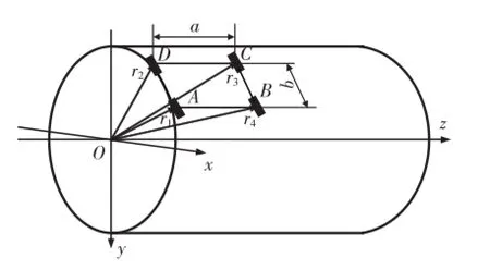
Fig.1 Coordinate graph for problem description of the curvature seam tracking of the four-wheeled mobile robot
The robot is set on the left of the pipe with a radius of R,and a coordinate system is established as shown in Fig.1. The central axis of the pipe is z-axis;the horizontal line across the centre of the section is x-axis;the plumb line across the centre of the section is y-axis.Each wheel is represented with a rectangle,and the coordinates of the center point of each rectangle indicates that of the corresponding wheel.According to the specific structure in Fig.1,the ideal coordinates of four points are described as follows.
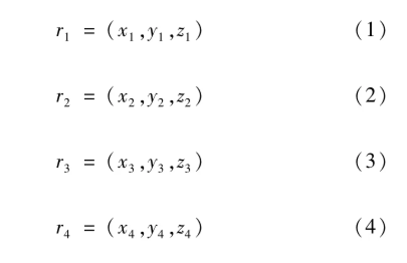
When the car body runs at the differential speed,assuming that the speed of right wheels is greater than that of left wheels,the car body will turn left and the deviation is generated.The algebraic relations for the robot’s falling off are derived quantificationally with analytical geometry in the following part.
Assuming that points A,B,D are known,the vertical distance R’from point C to z-axis can be solved.
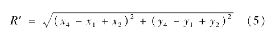
Since the coordinates of points A,B,D are all on the surface of the cylinder,as a result,
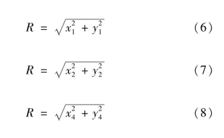

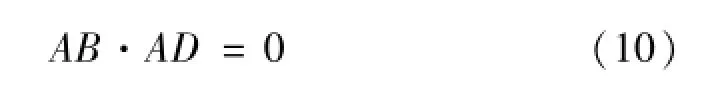
Substituting Eq.(6),(7),(8)into Eq.(5),the latter can be simplified as follows. Besides,the connection lines of the four points corresponding to the coordinates of the four wheels constitute a rectangle,which means that each line is perpendicular to its adjacent line.Therefore,Eq.(9)can be simplified with the inner product of vector AB and AD.
Thereinto,
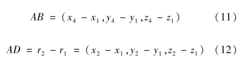
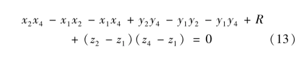
By substituting Eq.(11)and Eq.(12)into Eq.(10),
the following equation can be got.
Substituting Eq.(13)into Eq.(9),the result is as follows.
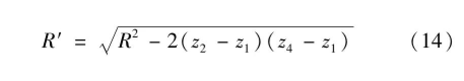
Conclusions can be reached as follows by the analysis of Eq.(14).
(1)If the robot is installed along the pipe generatrix and there are no deviations for the four wheels,z2-z1= 0 and R′=R can be obtained,which means the coordinates of point C are on the circular section of the pipe as the results of Eq.(6),(7),(8).
(2)If the robot is not installed along the pipe generatrix,a deviation for the car body appears.Assuming the deviation angle of the car body is θ,and a,b are the distances of AB and AD respectively,as shown in Fig.1.The follow equations can be obtained according to the projection relationship

Substituting Eq.(15),(16)into Eq.(14),the expression for the distance from point C to the center of the pipeline section can be obtained as follows

The deviation between the magnetic wheel and the surface of the pipe can be calculated with the following equation based on the result of Eq.(17)

2 Fuzzy control algorithm for curvature seam tracking of pipe welding
2.1Tracking control equation for the robot
The relationship between deviation and motion parameters of the robot is derived.Let ωRand ωLbe the angular speeds of the wheels on the right and left of the robot respectively,and ωRis greater than ωL.The position deviation of the car body caused by the differential speed is given by the equation c=ωRrt-ωLrt,and r is the radius of the wheel.The deviation angle can be derived as follows.
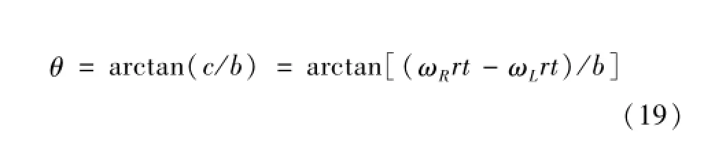
Substituting Eq.(19)into Eq.(18),and the tracking control equation is obtained as follows.
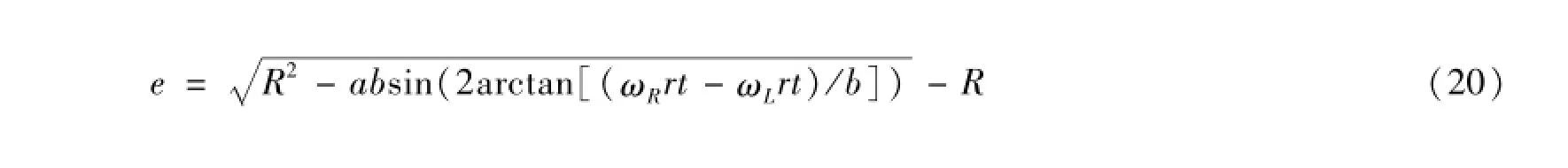
Eq.(20)is the deviation equation for curvature seam tracking of pipe welding by the robot.The equation shows that the deviation e can be calculated by the angular speeds ωRand ωLmeasured in real time and closed-loop control can be realized.
2.2Fuzzy control for curvature seam tracking of pipe welding
Taking the relationship between the falling off of the robot and the tracking deviation into account when the robot runs on the pipe,the threshold of deviation e and the relationship between motion of the robot and deviation e must be controlled strictly,so a dual-mode fuzzy control method based on the deviation is applied,which is shown in Fig.2.The fuzzy control method can be used to perform closed-loop control in real time when the four wheeled mobile robot runs on the pipe,and the problem of running stability of the robot on the pipe can be solved[7].
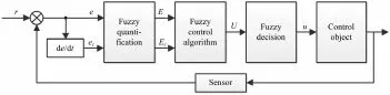
Fig.2 Schematic diagram of the dual-mode fuzzy control algorithm
2.3Fuzzy processing of control parameters
2.3.1Selection of fuzzy control word sets
The zero point is defined as the position that the center of a welding gun is aligned with the center of the seam. When the center of the welding gun is located on the left side of the seam,corresponding deviation linguistic variables are{positive small deviation(PS),positive middle deviation(PM),positive big deviation(PB)}.When the center of the welding gun is located on the right side of the seam,corresponding deviation linguistic variables are{negative big deviation(NB),negative middle deviation(NM),negative small deviation(NS)}.The variation of the deviation and the output control variable are described in a similar way to the deviation description.
2.3.2Selection of universe
According to the number of linguistic variables,the number of elements in the universe of the fuzzy set should be twice the total number of fuzzy linguistic variables or more generally,so as to ensure that the fuzzy sets can cover the universe preferably and avoid the phenomenon of out of control[8].
Based on the accuracy requirement of the seam tracking system and the number of linguistic variables defined in the previous section,the universes of input and output variables are defined as follows.
The universes of the input variables of deviation e,deviation variation ecand the output control variable for seam tracking are quantized into 13 levels,they are{-6,-5,-4,-3,-2,-1,0,1,2,3,4,5,6}.
Words applied by the fuzzy subsets of the input variables of deviation e,deviation variation ecand the output control variable are{NB,NM,NS,ZE,PS,PM,PB}.
Discrete universes are applied to decrease calculations in the control process,and the derived assignment table of the membership function is shown in Table 1.

Table 1 Assignment table of membership function of fuzzy variables corresponded with the seam tracking system
3 Verifications by simulation and welding experiments
3.1Fuzzy control algorithm for curvature seam tracking of pipe welding
The simulation verification to the fuzzy control algorithm proposed above is carried out by fuzzy inference system(FIS)integrated in MATLAB[9].
(1)Comparison of step signal tracking with different control algorithms by simulation
A step signal with an amplitude of 2.5 mm is taken as the input signal,and the classical PID system and the fuzzy control system are simulated by FIS in MATLAB.Simulation results are shown in Fig.3.Compared with the classical PID algorithm,the fuzzy control algorithm has a better dynamic performance on the step signal tracking with the characteristics of short adjustment time and small overshoot.
(2)Comparison of sinusoidal signal tracking with different control algorithms by simulation
A sinusoidal signal with a period of 2π and a peak-topeak value of 2 mm is taken as the input signal.The clas-sical PID system and the fuzzy control system are simulated in MATLAB respectively and tracking responses of the two systems are observed.The tracking response of the classical PID algorithm to the sinusoidal signal is shown in Fig.4 and that of the fuzzy control algorithm is shown in Fig.5. It is obvious that,compared with the tracking curve of the classic PID algorithm,the tracking curve of the fuzzy control algorithm is more smooth,and the fuzzy control algorithm has a more excellent performance in terms of accuracy and dynamic index.
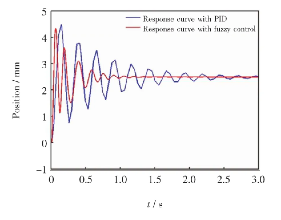
Fig.3 Step signal response curves with fuzzy control and classical PID control
3.2Welding tests for curvature seam tracking of pipe welding by the robot
An engineering prototype of the robot is developed based on the above theories,and the application experiments are carried out.Fig.6 shows the welding application of the robot at the construction site of a water supply project in Shanghai.The pipe seam is shown in Fig.7.The experimental results indicate that the welding quality is good with a preferable appearance of weld.

Fig.4 Tracking curve to sinusoidal signal based on the classical PID control
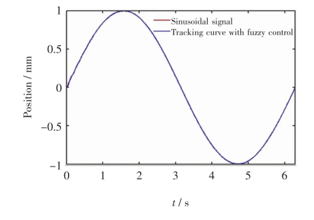
Fig.5 Tracking curve to sinusoidal signal based on the fuzzy control algorithm
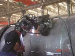
Fig.6 Field test with the mobile robot
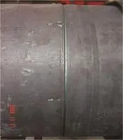
Fig.7 Seam on the pipe
4 Conclusions
(1)According tothefeaturesofcircumferential movement of the four-wheeled magnetic type mobile robot on the pipe,the reasons for the robot to fall off from the pipe at the moment of differential adjustment are analyzed. The space coordinate system and vector equations for movement of the robot on the pipe are established and the deviation equation for falling off of the robot is derived.
(2)The tracking control equation is derived for the relationship between the motion parameters of the robot and the deviation of falling off for the robot.A dual-mode fuzzy control method based on deviation is applied to realize closed-loop control to the four-wheeled mobile robot running on the pipe and the problem of running stability is solved.
(3)The simulations by FIS in MATLAB indicate that,compared with the classical PID system,the fuzzy control method has a better dynamic performance on the tracking response with the characteristics of short adjustment time and small overshoot.
(4)An engineering prototype of the mobile welding robot is developed according to the fuzzy control algorithm,and it has been applied successfully in the welding of water pipelines at the construction site of a water supply project. The seam quality is good with a preferable appearance of weld.
[1] Li T,Qian L,Wang W J.Technology of pipe welding.E-lectric Welding Machine,2007,37(12):32-35.(in Chinese)
[2] Yi Z Q,Yang M.Development prospect of welding construction and welding construction technology for long distance pipeline in China.China Petroleum and Chemical Standard and Quality,2012(6):249.(in Chinese)
[3] Ulrich N.Scientific methods in mobile robotics:quantitative analysis of agent behavior.Translated by Zhang W Z.Beijing:China Machine Press,2009.(in Chinese)
[4] Yun X P,Sarkar N.Unified equation of robotic systems with holonomic and nonholonomic constraints.IEEE Transactions on Robotics and Automation,1998,14(4):640-650.
[5] Wu Y X.Sliding mode control theory and its application in mobile manipulators.Guangzhou:South China University of Technology,2006.(in Chinese)
[6] Cai Z X.Robotics.Beijing:Tsinghua University Press,2009.(in Chinese)
[7] Kova cˇic'Z,Bogdan S.Fuzzy controller design theory and applications.Translated by Hu Y L,Zhang L Q,Liu Y J,Chen Y M.Beijing:China Machine Press,2010.(in Chinese)
[8] Li S Y.Fuzzy control.Harbin:Harbin Institute of Technology Press,2011.(in Chinese)
[9] Zhou P,Zhao X F.Mathematic modeling and simulation by MATLAB[M].Beijing:National Defence Industry Press,2009.(in Chinese)
*This paper is supported by National Natural Science Foundation of China(Grant No.51275051),the innovation and improvement plan of Beijing Education Commission(Grant No.TJSHG201510017023)
**Xue Yang,College of Energy and Power Engineering,Xi’an Jiaotong University,Xi’an,710049. Huang Junfen and Huang Jiqiang,Opto-Mechatronic Equipment Technology Beijing Area Major Laboratory,Beijing Institute of Petrochemical Technology,Beijing,102617. Zhang Xiang,College of Mechanical and Electrical Engineering,Beijing University of Chemical Technology,Beijing,100029. Huang Junfen,Corresponding author,E-mail:huangjunfen@bipt.edu.cn

- China Welding的其它文章
- Microstructure and mechanical properties of dissimilar joint between aluminum and aluminum-coated steel by cold metal transfer process*
- Metal transfer characteristics of tandem narrow gap GMAW for flat welding position*
- Study on parameters optimization in resistance spot welding of stainless steel with rectangular electrodes*
- Experimental study of weld position detection based on keyhole infrared image during high power fiber laser welding*
- Microstructure evolution in the weld metal region of a Ni-based Inconel 718 superalloy produced by tungsten inert gas welding
- Influences of acoustic field parameters on welding arc behavior in ultrasonic-MIG welding*