
Mid-Infrared Raman Fiber Lasers
2015-07-14 01:20:34CongLiuHanZhangChenWeiandYongLiu
Cong Liu, Han Zhang, Chen Wei, and Yong Liu
1. Introduction
The Raman fiber laser (RFL) is an important application of stimulated Raman scattering (SRS). It refers to a specific type of fiber laser that uses SRS, instead of stimulated electronic transitions, to amplify light. Among different types of RFLs, rare earth ions doped RFLs are of most importance and grow rapidly. In comparison with conventional chemical and solid-state lasers, RFLs have the advantages of high conversion efficiency, compactness,excellent beam quality, and great heat dissipation. Moreover,based on the principle of SRS, applying pump sources with different wavelengths can lead to outputs with longer Stokes wavelength and wider tunable wavelength range.
Near-infrared (1 μm to 2 μm) RFLs have been developed for years, the gain media are mainly oxide fibers such as silica fiber, phosphosilicate fiber, and germane silicate fiber. A cascaded RFL with output power of up to 301 W at 1480 nm has been reported[1]. This is also the RFL with the highest output power at 1.5 μm. The Shanghai Institute of Optics has demonstrated a RFL yielding 300 W at 1120 nm by using a new type of Yb3+-integrated Raman fiber amplifier[2]. Subsequently,with further system optimization, they successfully increased the output power by an order of magnitude to 1.3 kW[2]. Recently, National University of Defense Technology has built a RFL at 1090 nm by utilizing six cascading fiber lasers at 1018 nm to pump Yb3+-doped silica fiber. Eventually, the maximum output power of 2.14 kW has been obtained[3].
Mid-infrared (MIR) lasers with output wavelength of over 2 μm have wide spread and important applications in the fields of communication, national defense, biomedical science, and so on[4]. For instance, this kind of laser can be used in laser radar, laser ranging, and air communication as a result of the atmosphere transparent window ranging from 3 μm to 5 μm. Moreover, it locates in the operation band of most military detectors and is widely applied in many military fields including laser guidance, telemetry, and optical-electronic countermeasures. Additionally, since water molecules have a strong absorption peak at 2.94 μm wavelength, it can also be used in laser surgery exhibiting the advantages of rapid blood coagulation, small surgical wounds, and excellent hemostatic effects[5]. Traditional oxide fibers, especially silica fibers, are not suitable for MIR RFLs since they have a high transmission loss for the wavelength beyond 2 μm as a result of their high phonon energy. In order to obtain MIR wavelength output exceeding 2 μm, fibers with low phonon energy and small transmission loss in MIR band are required. Currently,fluoride and chalcogenide fibers are the most common gain media in MIR RFLs because of their excellent performances at that wavelength[6],[7].
This article introduces current research on MIR RFLs based on fluoride and chalcogenide fibers, respectively.The performances of both MIR RFLs have been compared and analyzed. In the end, the prospect of future development of MIR RFLs is discussed.
2. Theoretical Outline
In a RFL, the Raman gain coefficient (gR) is a basic parameter to describe the Raman scattering. It can be obtained by experimental measurement. The Raman on-off gain (G) is defined as the ratio of the output powers when the pump power is on and off[8]:
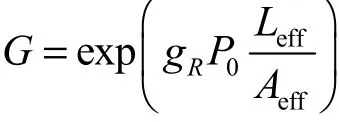
where P0isthe input puump power,Leffis thefiber efffective lengthh, and Aeffiss the fiber efffective modefield arrea. Thus gRccan be calculated after measuring the on-off gaain G. The Raaman gain coeefficient of fluuoride fibers iis 5.7 times of that oof silica fiberrs[9]. Chalcoggenide fibershave RRaman gain cooefficient 50times to 350times higherthan thhat of fluoridee fibers (20×110-12m/W to51×10-12m/WW for AAs-Se fibers aand 4.357×10--12m/W to 55.7×10⁻¹²m/WW for AAs-S fibers[10]]). The highh Raman gaiin coefficients of flluoride and chhalcogenide fiibers make itpossible to obtain RRa man laser ouutputs with shhort gain fiberss.
Accordingto the specifiic pump waveelength, the Stokes ouutput peak waavelength canbe theoreticallly calculatedwith thhe equation beelow:

w
where λpis the pump waveelength, λsisthe Stokes ouutput wwavelength, annd Δν is the RRaman frequency shift (RFSS). If itt is a second-oorder cascadestructure, thee first order Sttokes wwill be servedd as the pummp to obtainthe second-oorder Stokes laser.The RFS offluoride fibbers is about579 cmm-1[11], higherr than that off chalcogenidee fibers (240cm-1foor As-Se fiberrs and 340 cmm-1As-S fibeers[12]). It indicates thhat the achievved Stokes wwavelength offluoride fibers is loonger than thhat of chalcoogenide fiberss under the same puump conditionn.
3. Development of Fluoride Raman Fiber Laser
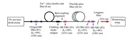
The most ccommon fluorride fiber is ZBBLAN fiber wwith a mmixture of 53mol.% ZrF4,20 mol.% BaaF2, 4 mol.%LaF3,3mol.% AlF3,and 20 mol.%% NaF. The ZZBLAN fiberhas a loow-loss transmission winddow rangingfrom 0.35 μm to 4μm. Currentlyy, rare earth ioons (such as TTm3+, Ho3+, orr Er3+)dooped fluoridefiber lasers ccan generate ooutput with 2 μm to 3μm wavelength[13]-[16]. Hoowever, the llack of MIRfiber BBragg grating(FBG) hindeers the furtheer developmeent of MMIR RFLs tosome extentt. Recently, tthe FBG hasbeen suuccessfully innscribed in afluoride fiberr using an 8000 nm feemtosecond laaser[17]and thhen the firstRFL based oon the flluoride fiber hhas been buillt[11]. The expperimental settup is shhown in Fig.1. Here, a Tmm3+-doped sillica fiber laseer was seerved as thepump sourcee of the RFLwhich providded a mmaximum CWW power of 96W at 1940 nmm. The Tm3+-ddoped siilica fiber lasser was pumpped by a BriightLase Ultrra-100 diiode array froom QPC Laseers Inc. operatting at 792 nmm and deelivering a maximum poweer of 35 W. TThen it was cooupled innto a 29 m lonng fluoride fiber.

Fig.1. Experimentaa l setup of 2185 nm RFL1].
TThe core diammeter and nummerical apertture (NA) ofthe fluoride fiber are6.5 μm and 0.23 μm, respectively. A pairr of FBGs are inscribeed in both endds of the fiberr. They were aalso thermmally annealed at 100°CC for 5 minuutes in orderto imprrove long terrm stability. FFig. 2 showsthe laser outpput powwer as a functiion of the launnched pump ppower. The laaser threshold was 3.88 W. The maaximum outpuut power of 5580 mWW only limitedby the availabble pump powwer was obtainned withh a slope effficiency of 229%. In addiition, it canbe obseerved that theefficiency shows a significcant roll-overfor pummp power in exxcess of 4 W aand decreasess to about 14%% at thepump powerr of 7 W. Thhis decreaseis the resultof specctral broadeniing inside thee laser cavityy. Moreover,the corrresponding nuumerical simullation was also performed aand showwn in Fig. 2.The simulatiion results maatches well with the eexperimental rresults.
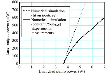
Fig.2. Laser outpuut power as a function of the launched pu mp power[11].
Fig. 3 presennts the Stokees output specctrum whenthe Stokes power wwas 280 mW,, and the innset showsthe transmittance speectra of the used FBGs. Itcan be observed thatthe Stokes peak wavelength of the RFL was 2185 nm.To ssum up, thouggh the MIR SStokes laser from the fluoride RFLL was obtainned, the leveels in termsof power and efficciencies werestill low.
Fi g. 4. Experime ntal setup of 2231 nm RFL[18].
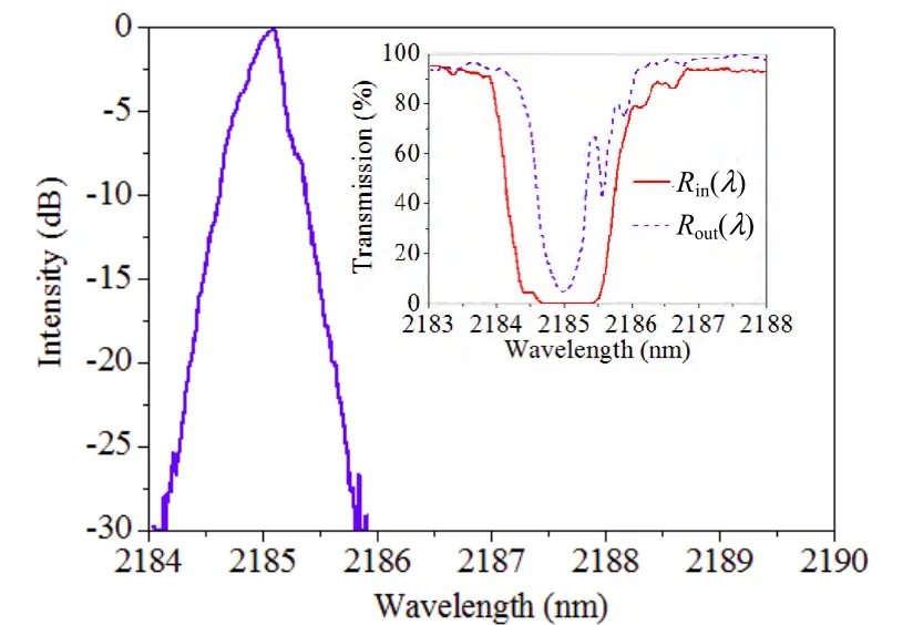
Fig. 3. Stokes ooutput spectrumm when the Stookes power waas 280 mW. Inset: transmmittance chart oof the pair of FBBGs[11].
Afterwardss, a watt-levvel RFL wwith an improved peerformance oover 2.2 μm bbased on thefluoride fibeer has beeen reported[118]. The experiimental setupis shown in Fig. 4.
The cavitystructure was basically saame as that shhown inn Fig. 1. Theonly differencce was that annother FBG wwhich haad a high refllectivity at thee pump wavellength of 1981 nm wwas written intto the outputend of the fluuoride fiber. OOther mmaterials usedin this experiiment were the same as thoose of Fig. 1. The 19881 nm pump llaser was obtaained by utilizzing a 7991 nm laserdiode of 366 W to pummp an 8 mlong TTm3+-doped doouble-clad sillica fiber. Theen it was couupled innto a 26 m lonng fluoride fibber. Fig. 5 illuustrates the ouutput poower
asafunnctionof pummp power. Thee maximum ouutput poowerof3.66Wwasobtaiinedwithasslopeefficienccyof 155% negligiblle. Meanwhile, the highreflectivity FFBGs ennhanced the innteraction streength of the ppump power in the RRaman cavityand compennsated the effficiency reduuction caaused by specctral broadeninng.

Fi g. 5. Stokes ou tput power as a function of pu mp power[18].
FFig. 6 (a) annd Fig. 6 (b)show the puump and Stokkes specctra, respectivvely. It can beobserved thaat no matter hhow theStokes powerr changes withh the pump poower, the Stokkes output peak wavelength is alwways locatedat 2231 nm.In addiition, both sppectra were bbroadened witth the increassed pummp power whhich is ubiquitous in a hiigh-power RFFL.Oncce the spectraa were broaddened beyondd the operation banddwidth of thee FBGs, the pperformanceof the RFL wwas serioously affectedd as a resultof laser poweer leakage. TThis wasmainly due too the low grouup velocity diispersion (GVVD)andthe reducedd FBG effecctive reflectivity. Sincethe fluoride fiber caan stably opeerate in the vvicinity of zero disppersion wavellength, the innfluence ofGVD couldbe neglligible. Meanwwhile, the higgh reflectivityFBGs enhanced theinteraction sttrength of thee pump poweer in the Raman caviity and compeensated the effficiency reduuction causedby specctral broadeninng.
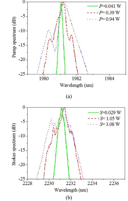
Fig.6. Spectra: (a) pump spectrum and (b) Stokes spectrum[18].
In this expeeriment, onlythe optical-too-optical efficciency with respect too the original 7791 nm pump has been obttained due to the limittation of the eembedded cavity. In practicce, the conversion effiiciency with reespect to the 11981 nm pump was higher.
4. Development of Chalcogenide Raman Fiber Laser
Chalcogeniide fibers maiinly consist oof chalcogenssuch ass S, Se, and TTe. Then extraa Ge, As, Sb, aand other elemments arre added. Commpared with AAs-S fibers, AAs-Se fibers haave a wwider MIR loww-loss transmiission windoww (0.8 μm to 77 μm foor As-S fiberand 1 μm to10 μm for Ass-Se fiber[4]). PP. A.TThielen et al.have gained tthe Raman ammplification bbased onn the As-Se ffiber at 1.5 μmm[19]. S. D. Jaackson et al.have obbtained a RFLL with the ouutput power oof 0.64 W at2062 nmm by utilizingg a 2051 nm TTm3+-doped ssilica fiber lasser to puump a 0.5 m llong As2Se3fiiber[20].
The develoopments of MMIR fiber laserrs over 3 μmlay a fooundation forr obtaining RRFLs with thhe longer Sttokes wwavelength. MM. Bernier et aal. have emplooyed a home-mmade 8000 nm femtoosecond pullse laser annd phase mmask teechnology tofabricate FBGGs in the loww-loss single-mmode chhalcogenide ffiber[21]andthen firstlyrealized theRFL yiielding the Sttokes outputwavelength oover 3 μm[22].The exxperimental seetup is shownn in Fig. 7.
They emplloyed a quassi-continuouswave Er3+-ddoped flluoride fiber llaser at 3.005μm as the puump source, aa pair off non-sphericaal lens (L1 annd L2) were uused to couple the puump into the3 m long As22S3single-modde fiber whichh has anumerical aperture (NA) oof 0.36, a corediameter of 44 μm,annd a claddinng diameterof 145 μm.. As a resullt of seelf-collimationn measuremeent, the pummp power couupled innto the Ramann cavity was oonly 26% of tthe original power(ii.e., the maximmum pump poower was 10 WW, the actual ppump poower was oonly 2.6 W),the 74% looss includedd the transmission looss of L1, L22, and the loww pass filter (LLPF)and the mismattch loss betweeen the incideent light and AAs2S3siingle-mode fibber.
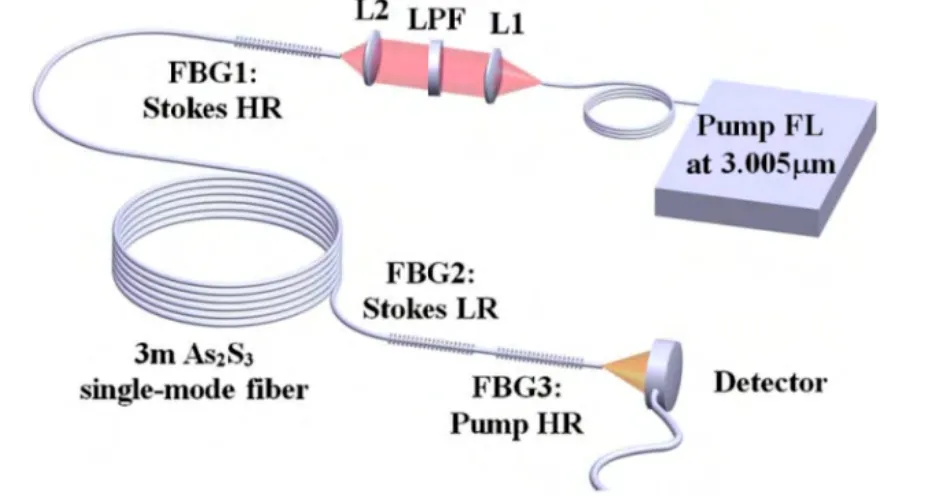
Fii g. 7. Experime ntal setup of 3.34 μm RFL[22].
Fig. 8 presents the spectra of the pump, FBGs,, and Stokes output. Comparedwith that of the pump,, the spectrum of Stokes output is significantlybroadened.
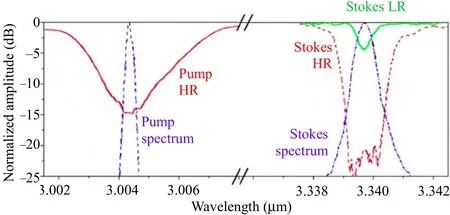
Fig.8. Spectra of thh e pump, FBGss, and Stokes[22].
Fig. 9 showsthe Stokes avverage power ((y-axis left) annd Stokes peak powwer (y-axis rright) as a ffunction of tthe launched pump aaverage powerr. It can be obbserved that the outpput powers inccrease linearlyy with the pump power. The maxximum averagge output poweer of 47 mW aand peak power of 0.6 W were obtained with aslope efficienncy of 39%. The corrresponding lasser threshold wwas 125 mW.

Fig.9. Stokes averrage power and peak power as a functionof launcched average puump power[22].
AAfterwards, MM. Bernier eet al. have demonstrateda secoond-order casscaded RFLbased on the chalcogenide fiberr. The Stokess wavelength was further extended to 3.77 μmwhich is alsoo the recordwavelength from MIR fiber laserrs at room teemperature[23]. The experimental setupis showwn in Fig. 10.
TThey employyed the samme quasi-conntinuous waave Er3++-doped fluoriide fiber laseer at 3.005 μmm as the pummp sourrce and thesame self-collimation mmeasurementas showwn in Fig. 7. It was estimmated that thhe pump powwer couppled into thecascaded Ramman cavity was only 38%of theoriginal pumpp power, themaximum puump power wwas 3.9W with a 1000% couplingg efficiency assumption. The gainn medium wass a piece of 2..8 m As2S3sinngle-mode fibber withh same parameeters as that uused in the aboove experimennt.Twoo pairs of FBGs directly innscribed in thhe chalcogenide fiberr were serveed as the lasser cavities oof the RFL.A transmission filteer of the outpuut end was ussed to filter oout the rresidual pumpp light and thee first-order Sttokes light.
FFig. 11 showws the spectraa of pump laaser, first-ordder Stokkes laser, annd second-ordder Stokes laaser. The peak wavvelengths of ffirst-order andd second-ordder Stokes laser are3.34 μm andd 3.766 μm,respectively.As the pump powwer increased,the spectrumm of first-ordder Stokes laser was obviouslybroadened whhile that of seecond-order Sttokes sttayed the samme. Fig. 12 sshows the avverage powerr and caalculated peakk power of thee second-ordeer Stokes laserr asa fuunction of thee average pummp power whhen the reflecttivity off the output ccoupler (OC) aat 3.77 μm was 98%, 92%, and 800%, respectivvely. It can bbe observed thhat both thelaser threshold andslope efficienncy increase wwith the increased reflectivity of tthe OC. Thecalculated sloope efficiency was 1.1%, 3.5%, aand 8.3%, resspectively. WWhen the OCwith 80% reflectivity wwas utilized, tthe maximumStokes averaage output power of9 mW corresponding to apeak powerof 114mW was obbtained at the launched ppump powerof 371mW. In the nnumerical stimmulation, whenn the reflectiviity of OC at 3.77 μmm was reducedto 60%, a peaak output power of 1158 mW witth a slope efficiency of12% couldbe acquuired. Howeveer, it cannot bbe realized exxperimentallyas a reesult of acciidentally nonnlinear fiberdamage when expeeriencing the cc ycle process of thermal annnealing.
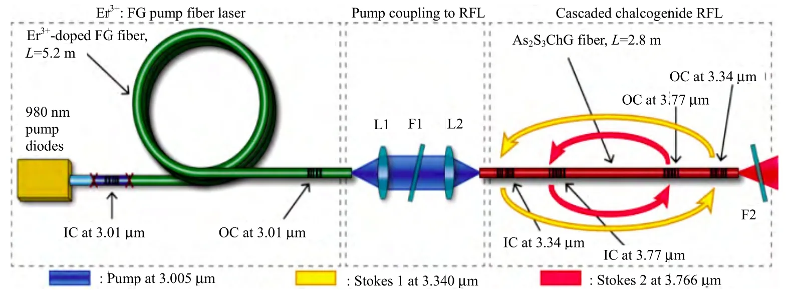
Fi g. 10. Experimental setup of 3.77 μm cascad ed RFL[23].
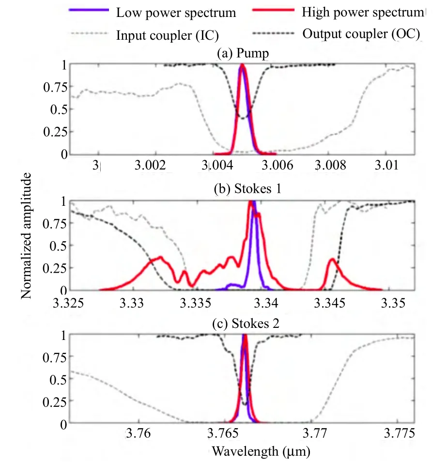
Fig. 11. Spectrum: (a) pump spectrum, (b) Sto kes 1 spectrum, and(c) Stokes 2 spectrum[23].
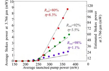
Fig. 12. Second-order Stokes average power and peak power as a function of the average pump power[23].
TThe obtainedd wavelengthof 3.766 μmm is the longeest Stokes wavelenggth in RFLsfrom domesstic researchto foreign research.Above results present thee Stokes outpput power and slopee efficiencywere very low, it canbe improved by thee followingaspects: Redducing the loss caussed by FBGss (every FBGG has beentested and the averrage loss wwas 3% to4%), suppreessing spectral broaadening of thee first-order Sttokes light, annd so on.
5. Conclusions
WWe have brieffly introducedd the recent developments oon MIRR RFLs. Therare earth ioons doped oxxide RFLs haave reacched hundredss of watts orr even kilowwatts level wiith Stokkes wavelenngth less thhan 2 μm.Fluoride annd challcogenide RFLLs have yieldded the Ramaan laser outpuuts withh longer wavelength beyondd 2 μm. The ooutput powersof fluoride RFLs hhave reachedd watt-levelwith emissioon wavvelength of 2μm to 3 μm.The outputpower levelof challcogenide RFLLs is relativelly low at millliwatt level bbut withh a longerStokes waveelength of uup to 3.77 µmm.Commpared withthe researchlevel abroadd, the domesttic research in theMIR RFLss is still ata preliminaary statee[24]-[28]. Thouugh some proggresses on MIRR RFLs beyonnd 3 μmm have beenachieved, theere are still mmany challengges remaaining. In oorder to reallize high poower and higgh efficciency operatiion of RFLs aat longer MIRR wavelengths, a seriees of efforts sshould be depployed to imprrove the quality of nnonlinear MIRR fiber, fabriicate high-perrformance MIR all-ffiber passivecomponentss, increase thhe power, and exteend the outputwavelength oof the pump soource, etc.
[1] V. R. Supradeepa and J. W. Nicholson, “Power scaling of high-efficiency 1.5 μm cascaded Raman fiber lasers,” Optics Letters, vol. 38, no. 14, pp. 2538-2541, 2013.
[2] L. Zhang, C. Liu, H. Jiang, Y. Qi, B. He, J. Zhou, and Y.Feng, “1.3 kW Raman fiber laser,” Chinese Journal of Lasers, vol. 6, pp. 22-22, Mar. 2014 (in Chinese).
[3] H. Xiao, J. Leng, H. Zhang, L. Huang, S. Guo, P. Zhou, and J. Chen, “2.14 kW cascade-pumped Raman fiber amplifier,”High Power Laser and Particle Beams, vol. 27, no. 1, pp.010103-1-0.0103-2, 2015 (in Chinese).
[4] J. S. Sanghera, L. B. Shaw, L.E. Busse, et al., “Infrared optical fibers and their applications,” in Proc. 1999 SPIE Conf., Boston, 1999, pp. 38-49.
[5] M. Pollnau and S. D. Jackson, Advances in Mid-Infrared Fiber Lasers, Berlin: Springer, 2008, pp. 315-346.
[6] P. W. France, M. G. Drexhage, and J. M. Parker, Fluoride Glass Optical Fibers, Glasgow: Blackie, 1990, ch. 1.
[7] L. B. Shaw, B. Cole, P. A. Thielen, J. S. Sanghera, and L. D.Aggarwal, “Mid-wave IR and long-wave IR laser potential of rare-earth doped chalcogenide glass fiber,” IEEE Journal of Quantum Electronics, vol. 48, no. 9, pp. 1127-1137,2001.
[8] G. P. Agrawal, Nonlinear Fiber Optics, 5th ed. Oxford, U.K:Academic Press, 2013, ch. 8, pp. 299.
[9] V. Fortin, M. Bernier, J. Carrier, and R. Vallee, “Fluoride glass Raman fiber laser at 2185 nm,” Optics Letters, vol. 36,no. 21, pp. 4152-4154, 2011.
[10] R. T. White and T. M. Monro, “Cascaded Raman shifting of high-peak-power nanosecond pulses in As2S3and As2Se3optical fibers,” Optics Letter, vol. 36, no. 12, pp.2351-2353, 2011.
[11] T. Mizunami, H. Iwashita, and K. Takagi, “Gain saturation characteristics of Raman amplification in silica and fluoride glass optical fibers,” Optics Communications, vol. 97, no.1-2, pp. 74-78, 1993.
[12] J. S. Sanghera, L. Shaw, P. Pureza, et al., “Nonlinear properties of chalcogenide glass fiber,” Intl. Journal of Applied Glass Science, vol. 1, no. 3, pp. 296-308, 2010.
[13] Y. D. Huang, M. Mortier, and F. Auzel, “Stark level analysis for Er3+-doped ZBLAN glass,” Optical Materials, vol. 17,no. 4, pp. 501-511, 2001.
[14] S. D. Jackson, “Single-transverse-mode 2.5 W holmiumdoped fluoride fiber laser operating at 2.86 μm,” Optics Letters, vol. 29, no. 4, pp. 334-336, 2004.
[15] D. Faucher, M. Bernier, N. Caron, and R. Vallee,“Erbium-doped all-fiber laser at 2.94 μm,” Optics Letters,vol. 34, no. 21, pp. 3313-3315, 2009.
[16] S. D. Jackson, “High-power and highly efficient diodecladding-pumped holmium-doped fluoride fiber laser operating at 2.94 μm,” Optics Letters, vol. 34, no. 15, pp.2327-2329, 2009.
[17] M. Bemier, D. Faucher, R.Vallee, A. Saliminia, G. Androz, Y.Sheng, and S. L. Chin, “Bragg gratings photoinduced in ZBLAN fibers by femtosecond pulses at 800 nm,” Optics Letters, vol. 32, no. 5, pp. 454-456, 2007.
[18] V. Fortin, M. Bernier, D. Faucher, J. Carrier, and R. Vallee,“3.7 W fluoride glass Raman fiber laser operating at 2231 nm,” Optics Express, vol. 20, no. 17, pp. 19412-19419,2012.
[19] P. A. Thielen, L. B. Shaw, P. C. Pureza, V. Q. Nguyen, J. S.Sanghera, and L. D. Aggarwal, “Small-core As-Se fiber for Raman amplification,” Optics Letters, vol. 28, no. 16, pp.1406-1408, 2003.
[20] S. D. Jackson and G. Sanchez, “A chalcogenide glass Raman fiber laser,” Applied Physics Letters, vol. 88, pp.221106-221109, May 2006.
[21] M. Bernier, M. El-Amraoui, J. F. Couillard, Y. Messaddeq,and R. Vallee, “Writing of Bragg gratings through the polymer jacket of low-loss As2S3fibers using femtosecond pulses at 800 nm,” Optics Letters, vol. 37, no. 18, pp.3900-3902, 2012.
[22] M. Bernier, M. Fortin, N.Caron, M. El-Amraoui, Y.Messaddeq, and R. Vallee, “Mid-infrared chalcogenide glass Raman fiber laser,” Optics Letters, vol. 38, no. 2, pp.127-129, 2013.
[23] M. Bernier, V. Fortin, M. El-Amraoui, Y. Messaddeq, and R.Vallee, “3.77 μm fiber laser based on cascaded Raman gain in a chalcogenide glass fiber,” Optics Letters, vol. 39, no. 7,pp. 2052-2055, 2014.
[24] G. Qin, S. Huang, H. Feng, A. Shirakawa, M. Musha, and K.I. Ueda, “Power scaling of Tm3+-doped ZBLAN blue upconversion fiber lasers modeling and experiments,” Applied Physics, vol. 82, no. 1, pp. 65-70, 2006.
[25] J. Li, Y. Chen, M. Chen, et al., “Theoretical analysis and heat dissipation of mid-infrared chalcogenide fiber Raman laser,” Optics Communications, vol. 284, no.5, pp.1278-1283, 2011.
[26] J. Li, Z. Ou, Z. Dai, Z. Peng, L. Zhang, and Y. Liu,“Theoretical analysis and design of Mid-infrared ZBLAN Raman fiber laser,” Infrared and Laser Engineering, vol. 40,no. 8, pp. 1432-1437, 2011 (in Chinese).
[27] H.-Y. Luo, J.-F. Li, J. Li, Y.-L. He, and Y. Liu, “Numerical modeling and optimization of mid-infrared fluoride glass Raman fiber lasers pumped by Tm3+-doped fiber laser,”IEEE Photonics Journal, vol. 5, no. 2, pp. 2700211, 2013.
[28] Y. Wang, Z. Q. Luo, F. Xiong, Z. P. Cai, and H. Y. Xu,“Numerical optimization of 3-5 μm mid-infrared ZBLAN fiber Raman lasers,” Laser & Optoelectronics Progress, vol.51, pp. 061405, Mar. 2014 (in Chinese).
 Journal of Electronic Science and Technology2015年4期
- Journal of Electronic Science and Technology的其它文章
- Energy Optimization of Savonius Vertical Axis Wind Turbine
- Embedded TLS 1.2 Implementation for Smart Metering & Smart Grid Applications
- Impact of Business Practices on Individual Energy Consumption
- Changing Energy Consumption Behaviour:Individuals’ Responsibility and Government Role
- UV-Inscribed Optical Fiber Gratings in Mid-IR Range and Their Laser Applications
- Powerful 2 μm Silica Fiber Sources: A Review of Recent Progress and Prospects