Research and implementation of intelligent alarm transceiver
Haobo long XiaolingTian
Abstract: To design and implement a intelligent alarm transceiver, the sensor, such as temperature, voltage, video check. is used in transceiver. Then it analyses real-time acquisition data of sensor, if the transceiver is not working normally, and the results are sent to the host computer. And the latter send fault information to user by mobile phone. During this period, without artificial participation, to achieve the purpose of intelligent warning. it can improve the maintenance efficiency of transceiver.
Key words: security monitor, intelligent alarm, sensor technology, message alarm
1、Introduction
The application domain of video monitoring system is more and more widely, especially the "Ping An City" promotes the rapid growth of video surveillance market, and the monitoring system of the scale are constantly expanding. The optical transceiver is the core of the monitoring system of transmission equipment, when the fault occurs, the whole system do not work normally, therefore, finding fault in the optical transceiver is very important, for the normal running of the whole system in the past, if the system fails, people often cannot discover it, and due to the large scale , investigation is time-consuming , laborious and low efficiency.
To design and realize the optical transceiver based on sensor and network technology and it can report its failure to system maintainer. The built-in temperature, humidity and voltage sensors can get real-time equipment information, and then transmit to the client, based on this information the latter will determine whether the device is normal. If the equipment failure, the client will tell the system maintainer through the mobile phone short message, voice, interface and acousto-optic four ways .During this time, there is not manual participation and it is finished by the control system automatically.
2、The composition of intelligent alarm transceiver and its system
The system is made up of three layer, and adjacent two layer can communicate by network. the first layer is network management, the second layer is transmitting management, the third layer is video acquisition and management. In every layer, the equipment has unique address.
In network management layer, the core equipment is network management card, and it has the unique IP address and can convert 485 signal to Ethernet signal.
In transmitting management layer, the core equipment is optical transceiver,the latter belong to the same network management card has the unique address. and its address is set from 0-255 by dial switch. following the same network management card, up to 256 optical transceivers. Transceiver can tell user its temperature , voltage, power and fiber state.
In video acquisition and management layer, the core equipment is the front-end equipment , for example, the high speed ball or the camera. and its address is set from 1-32 (the maximum channel number of current video optical transceiver is 32 ).
the sensor in camera collected the real-time state data of camera and then transmit to optical transceiver by 485 data line. and these data is transmitted to client at last by transceivers and network management card. if the fault happen, the latter will tell the user what happen through the short message, acousto-optic and speech.
3、the hardware design of intelligent warning optical transceiver
The hardware part includes the realization of the detection of temperature ,voltage, power and fiber optical.
3.1the overall hardware structure design
the hardware structure is made up of MCU,I/O port and other component.
the main control MCU is STC12LE5A08S2,this chip has 2 independent serial port, and can simulate a serial port through the I/O port , so, total of 3 serial port. the first is responsible for communication with front-end equipment. Through this port, MCU can acquire the state data of front-end equipment, the second for 485 data communication, through it, MCU can communicate with higher network management card. the last for the acquisition of itself state data, through it, MCU can get the itself state data, such as temperature, voltage and video state.
3.2temperature detection scheme
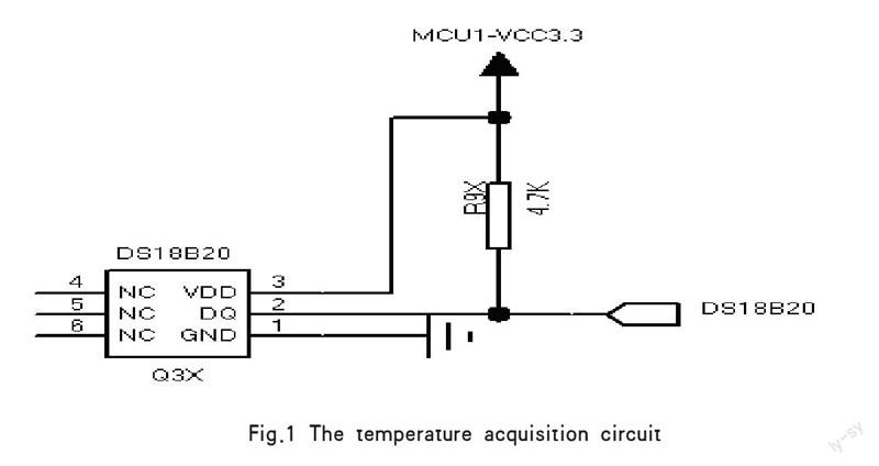
Temperature acquisition is implemented by the DS18B20 scheme, the hardware structure diagram is the following figure 1:
In this scenario, the DS18B20 chip get real-time temperature data and then stored in the internal registers, and the controller convert the binary data to Decimal data.
3.3voltage detection scheme
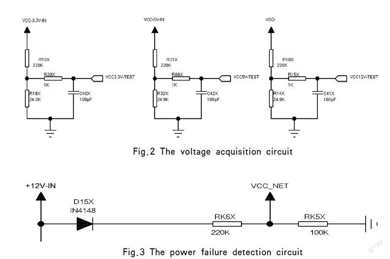
The voltage detection circuit as shown in the following figure 2:
Adetection circuit get voltage division sampling through the resistor and transmit it to the I/O port of the SCM, and then the internal microcontroller A/D
Circuit to calculate the actual voltage.
3.4power and optical detection scheme
power and optical detection circuit as shown in Figure 3, the CPLD in the transmitter detected the power failure signal
Fig.1 The temperature acquisition circuit
Fig.2 The voltage acquisition circuit
Fig.3 The power failure detection circuit
and then transmit a string of data to the CPLD of receiver that is responsible for decoding, if the MCU of receiver receives the power failure of transmitter and then it will query the state of optical fiber every 200 MS. If the optical fiber is normal, the MCU get the conclusion of power failure of transmitter. When the MCU of receiver is available, it poll state of optical fiber. If get fiber loss and don't receive the power failure of transmitter. The MCU will think optical fiber is broken.
4、Summary
Intelligent warning optical transceiver has realized the real-time monitoring of the state itself by sensor technology, and intelligent analysis of state data.
when it failed, it can notify the system maintenance personnel. So it improves work efficiency, especially in the monitoring system of the larger. However, when client polls the transceiver, and the latter transmit the data to client. And it cannot take the initiative to report the finding problems, which will be resolved in follow-up version.
References
[1]Liu Hailiang, Cao Jianian, Guo Fengli. Research and implementation of embedded intelligent home security system[J]. application technology, 2011.
[2]Li Ziyun. Intelligent home security system based on wireless network. The microprocessor, 2012.
[3]Jia Shifeng. The principle of sensor and sensor technology [M]. Beijing: Mechanical Industry Press, 2009.
[4]Xu Xiejun sensor and detection technique of [M]. Beijing: Publishing House of electronics industry, 2011.
[5]Xu Jian remote control security system design based on 3G wireless [J]. microcomputer and application, 2012

