Flowability and Infrared Interference Properties of Modified Graphite Flake with Hydrophobic Nano-silica
NING Gong-tao, LI Ping, CUI Yu-ling, LI Shi-chuan, TANG Run-ze, ZHOU Zun-ning
(1. National Key Laboratory of Mechatronic Engineering and Control, Beijing Institute of Technology, Beijing 100081, China; 2. 73921 Troops, Nanjing 210016, China; 3. State Key Laboratory of Explosion Science and Technology, Beijing Institute of Technology, Beijing 100081, China)
1 Introduction
The advent of more advanced infrared (IR) sensors containing sophisticated target acquisition and guidance systems spurred the development of smokes that attenuate light in the IR wavelengths[1-2]. A variety of offensive and defensive systems and materials are employed on the battlefield. The most popular IR smokes are solid materials of graphite flakes that have good IR absorption properties because of their moderately strong molecular vibrations in the IR region[3-4].
Graphite flake material must be disseminated and airborne to be effective as an electromagnetic obscurant. The graphite flake aerosols are mechanically generated using compressed-air systems. The powder is directly delivered to the air-ejector of smoke generators. The demand for effective graphite flake aerosols formulation is increased for better delivery efficiency and dispersion capability. The flowability of graphite flake particles is particularly important because it influences the delivery process and dissemination efficiency. However, most studies are focused on graphite flake particles with various sizes to improve the IR extinction performance[5-6]. Graphite flakes used for IR smokes are very easy to be combined with atmospheric water because of having a greater specific surface area and smaller particle size. If graphite flakes are coated by water or formed agglomerates between graphite flake particles, their settling velocity will be accelerated and infrared extinction performance will be degraded[7-8].
Most literatures have shown that hydrophobic nano-particles may modify powders and improve the flowability between powder particles[5, 7-10]. The research presented in this paper focuses on the evaluation of the flowability and extinction performance of modified graphite flakes with hydrophobic nano-silica. The index of flowability and IR spectrum transmittance of surface modification of graphite flakes were determined and compared with those of unmodified graphite flake particles.
2 Experimental
2.1 Materials
Hydrophobic nano-silica(AEROSIL R202) powder was chosen as guest particles supplied by German Evonik Degussa. The nano-silica has highly hydrophobic characteristic because its —SiOSi(CH3)3groups(Scheme 1). As shown in Scheme 1, silica particle with lots of —SiOH groups is sensitive to the variations of humidity. The median particle size of hydrophobic nano-silica,D50is about 15 nm. This material is a fine, white, cohesive and hydrophobic powder widely used in medicine and catalyst, etc.

Scheme 1
Graphite is a soft-scale form of carbon that can be natural or synthetic in origin. Natural graphite was provided by Chinese Qingdao OER graphite Co. LTD and chosen as host particles. The chemical composition of the bulk powder is predominantly carbon with trace impurities totaling less 1% by mass. The trace impurities include small quantities of silica, aluminum, iron, calcium, titanium, and magnesium. Fig.1 shows a TEM picture of nature graphite particles. Their surface seems to have fish scale-like form.D50is about 6 μm.
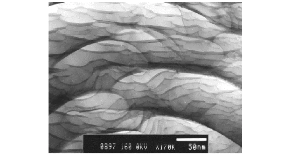
Fig.1 TEM image of nature graphite flake
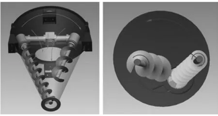
Fig.2 Model DSH-0.5 double screw conical mixer
2.2 Modifying Processes
A double screw conical mixer (Model DSH-0.5) was chosen to perform a dry coating in this study. This apparatus was defined as a high shear mixer, manufactured by Shanghai Shenli machinery Co. Ltd, China. As it can be seen from Fig.2, it rotated around its axes by right of two internal asymmetric spirals which was installed on the cantilever. Mean while, the rotational force from the cantilever drove two spiral doing revolution around conical chamber axle wire. It applied high mechanical impact and shearing forces on the particles in order to break the fine agglomerates and coated them on the host particles. This way could full the bottom gap and form a convective circulation. The dry coating method was also used successfully for dry particle coating experiment[9-11]. The operating condition was 1500 r·min-1for 40 min at room temperature.
2.3 Characterization
The various characterization methods were used after dry particle coating. The surface morphology of the particles was observed by scanning electron microscopy (Hitachi Model S-4800). The powder tester (TC-1000/1001) was used to examine the flowability of the unmodified and modified samples. The 20 m3(6.1 m×2.0 m×1.8 m) smoke chamber used to measure the performance parameters such as IR spectrum transmittance of aerosol, settling velocity, mass concentration was shown in Fig. 3 with the full smoke characterization instrument configuration. Glass fiber filters, a rotometer and vacuum pump were used to make aerosol concentration measurements at a flow rate of 36 liters per minute. The aerosol transmittance over the wavelength range of 1.34-13.94 μm was measured by an IR spectrometer (Model 12-550 MarkⅢ, USA) with HgCdTe detector operated at liquid nitrogen temperature.
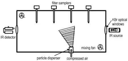
Fig.3 Schematic diagram of the particles chamber showing the instruments
A known mass (approximately 30 g) of particles was placed inside the powder disperser, which was connected to a compressed air tank through a hose and nozzle. The nozzle was operated at 202.6 MPa to disperse and deaggregate powders to produce an aerosol of primary particles. Two mixing fans were operated continuously in the chamber at a low speed to maintain uniform concentration and provided a level of turbulence driving re-aerosolization and impaction approximating those components of aerosol deposition in the battlefield. Spectral scans started to record data after finished powder dissemination, at the same time, the aerosol mass concentration measurement was started. Repeated measurements were made by stopping 1 min after finished particles sampling.
3 Results and Discussion
3.1 The Flow Property of Graphite Flake Particles
The flow property of particles is a very important factor in the process of powder handling such as storage, portage and transfer. The phrase “good flow behaviour” usually means that a bulk solid flows easily, i.e., it does not consolidate much and flows out of a silo or a hopper due to the force of gravity alone, and no flow promoting devices are required. Products are “poorly flowing” if they experience flow obstructions or consolidate during storage or transport. Carr[12]suggested a method for evaluating the flowability from his experience on the handling of various powders. The flowability (Fw) was calculated using the sum of indices suggested by Carr for the angle of repose (θr), angle of spatula (θs), degree of uniform (Uf) and compressibility (Cp).Fwzis a common way to characterize the flow behavior of particles. HigherFwzvalues indicate better flowability. The flowability index can be calculated by Eq. (1):
Fwz=θrz+θsz+Cpz+Ufz
(1)
whereFwzis the flowability index;θrzis the angle of repose index;θszthe angle of spatula index;Cpzis the compressibility index andUfzis the degree of uniform index.
Table 1 summarizes the values of the flowability index of the unmodified and modified graphite flake calculated using the angle of repose index, angle of spatula index and compressibility index according to powder evaluation method suggested by Carr. The angle of repose and compressibility of the modified graphite flake gradually reduce with increasing in the mass of nano-SiO2,indicatinganagglomerationdecreasesbetween the graphite flake particles. When the nano-silica mass ratio is 4.0%, the value ofθrreaches the minimum andFwzbecomes maximum. This means that the flowability is improved through surface treatment.
Table 1 Flowability of the unmodified and modified graphite flake

massofnano-silica/%θr/(°)θrzθs/(°)θszCp/%CpzUfUfzFwz046.014.577.0744.02.02.242346.5145.715.071.51242.72.02.242352.0245.715.070.81236.75.02.242355.0344.316.068.01236.07.02.242358.0443.716.069.31230.710.02.242361.0546.014.574.71032.09.52.242357.0
3.2 Graphite Flakes Aerosol Properties
Each value of mass concentration represents the mean of four different sampling locations (see Table 2). In order to obtain the settling velocity, the following equation is employed based on a series of two filter concentration measurements[13]
(2)
whereνdis the settling velocity in m·s-1,His the chamber height in m,C(t1) is the mass concentration taken over time intervalst1to (t1+1),in g·m-3andC(t2) is the mass concentration taken over time intervalst2to (t2+1)in g·m-3.
Table 2 Mass concentration and settling velocity of particles in chamber

massfractionofnano-silica/%massconcentrationatdifferenttimeintervals/g·m-30-1min2-3min4-5min6-7minaveragemassconcentrationatdifferenttimeintervals/g·m-301.13190.81560.63250.51252.28811.09440.82560.65130.53562.13421.13060.94310.79060.66001.58731.07620.89250.76380.65381.40141.12810.93630.82630.71311.12551.05620.85310.66810.58312.200
The IR spectrum radiance values measured by the Mark III spectrometer are converted to transmittance (T(λ) values using Eq.(3).
(3)

The values of the band-averaged transmittance of unmodified and modified graphite flake aerosols are calculated using Eq.(4).
(4)
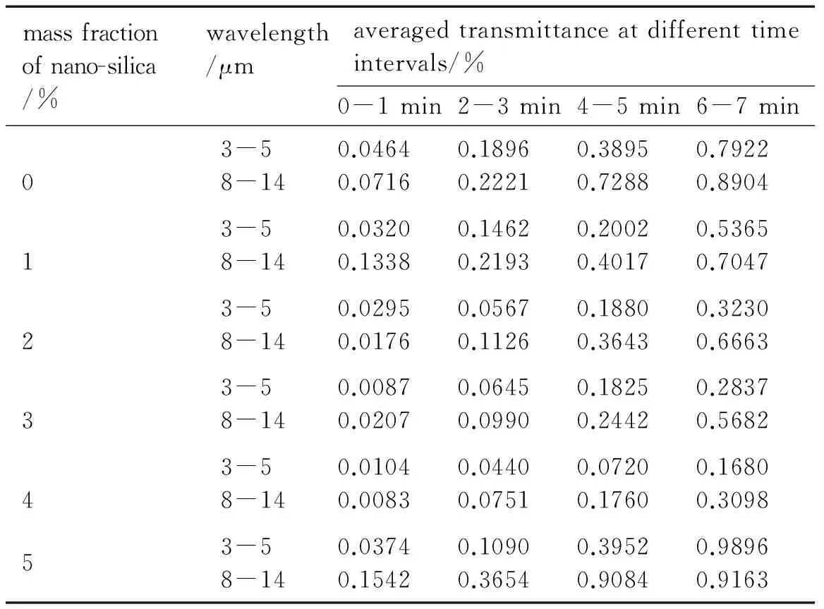
Table 3 summarizes the values of the band-averaged transmittance of unmodified and modified graphite flake aerosols.
The data of band-averaged transmittance of particles in Table 3 gradually decrease with increasing the mass of nano-silica. Fig.4 shows the IR spectrum transmittance of unmodified and modified graphite flake with the nano-SiO2mass ratio of 4.0% at 4-5 min. The mean transmittance value of modified graphite flake is 0.072% in the range of 3-5 μm and 0.176% in the range of 8-14 μm, which is significantly different from 0.3895% in the range of 3-5 μm and 0.7288% in the range of 8-12 μm of unmodified graphite flake. Many factors can influence the IR extinction properties of obscurants, including the conductivity, air concentration, and morphology, etc[14].
Table 3 Band-averaged transmittance of graphite flake aerosols in particles chamber
massfractionofnano-silica/%wavelength/μmaveragedtransmittanceatdifferenttimeintervals/%0-1min2-3min4-5min6-7min03-58-140.04640.07160.18960.22210.38950.72880.79220.890413-58-140.03200.13380.14620.21930.20020.40170.53650.704723-58-140.02950.01760.05670.11260.18800.36430.32300.666333-58-140.00870.02070.06450.09900.18250.24420.28370.568243-58-140.01040.00830.04400.07510.07200.17600.16800.309853-58-140.03740.15420.10900.36540.39520.90840.98960.9163
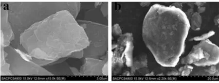
Morphology is particularly important because it influences the coagulation process and removal of particles from the air[15-16]. The surface morphology of modified graphite flake with nano-silica in Fig.5b is smoother than unmodified graphite flake in Fig.5a. That can help the particles to have better flowability. This change minimizes the coagulation between the graphite flake particles and lowers the settling velocity of particles when larger clusters of graphite flake particulates can not be formed. The settling velocity deceases from 2.288×10⁻³m·s-1of unmodified graphite flake to 1.125×10⁻³m·s-1of modified graphite flake (see Table 2). However, after this optimal amount of nano-silica, the settling velocity increases. The reason for this increase is unclear and further studies are needed in order to clarify the mechanism behind.

Fig.4 IR spectra transmittances of unmodified and modified graphite flake particles at 4-5 min
a. aloneb. treated in DSH mixer
Fig.5 SEM (Model S-4800) images of graphite flake treated with silica
4 Conclusions
(1) A method of modifying the graphite flake particle surface with hydrophobic nano-SiO2using the dry particle coating process is presented.
(2)The Carr′s flowability index of graphite flake particulates modified with hydrophobic nano-silica in mass ratio of 4.0% is the highest, reaching 61.
(3) This physical modification makes the settling velocity of modified graphite flake decrease from 2.288×10⁻³m·s-1before modification to 1.125×10⁻³m·s-1after modification and the duration of graphite flake particles floating in air increases.
Acknowledgement:The authors are grateful to the State Key Laboratory of Explosion Science and Technology (Beijing Institute of Technology) for experimental support of projects.
[1] Albertoni A. Long wave infrared metamaterials and nano-materials design, simulation and laboratory test for target camouflage in the defence application [C] ∥Proc of Electro-Optical and Infrared Systems: Technology and Applications VIII. Prague: SPIE, 2011, 8185: 1-19.
[2] Viau C R. Expendable countermeasure effectiveness against imaging infrared guided threats[R]. Tactical Technologies Inc, 2012
[3] Mukhopadhyay P, Gupta R K. Graphite, graphene and their polymer nanocomposites [M]. New York: CRC press, 2013: 1-10.
[4] Petrov M B. Modeling of magnetoelectric effects in composites [M]. New York: Springer, 2014: 10-33.
[5] Pjesky S C, Maghirang R G. Infrared extinction properties of nanostructured and conventional particles [J].ParticulateScienceandTechnology, 2012, 30(2): 103-118.
[6] Yadav A, Kumar R, Bhatia G, et al. Development of mesophase pitch derived high thermal conductivity graphite foam using a template method [J].Carbon, 2011, 49(11): 3622-3630.
[7] Focke W F, Badenhorst H, Ramjee S, et al. Graphite foam from pitch and expandable graphite [J].Carbon, 2014, 73: 41-50.
[8] CHEN Zong-sheng, SHI Jia-ming, YUAN Zhong-cai, et al. Effect of wrapped liquid on IR extinction characteristics of graphite spheres [J].TheChineseJournalofInfrared, 2007, 28(12): 30-33.
[9] CHIU Chih-cheng, LO Jen-chieh, TENG Mao-hua. A novel high efficiency method for the synthesis of graphite encapsulated metal (GEM) nanoparticles [J].Diamond&RelatedMaterials, 2012, 24: 179-183.
[10] Akira S, Eric S, Philippe G, et al. Experiment and simulation of dry particle coating [R]. Granulation Conference Lausanne, Zwitzerland, 2011.
[11] Ouabbas Y, Dodds J, Galet L, et al. Particle-particle coating in a cyclomix impact mixer [J].PowderTechnology, 2009, 189(2): 245-252.
[12] Honda H, Kimura M, Honda F, et al. Preparation of monolayer particle modified powder by the dry impact blending process utilizing mechanochemical treatment[J].ColloidsandSurfacesA:PhysicochemicalandEngineeringAspects, 1994, 82(2): 117-128.
[13] Carr R L. Classifying flow properties of solids[J].ChemicalEngineering, 1965, 72: 69-72.
[14] Embury J F, Walker D L, Zimmermann C J. Screening smoke performance of commercially available powders I. Infrared screening by graphite flake [R]. No: ERDEC-TR-093, Edgewood Research Development & Engineering Center, Edgewood, MD, USA, 1993.
[15] Appleyard P G, Davies N. Modeling infrared extinction of high aspect ratio, highly conducting small particles[J].JournalofOpticsA, 2004, 6(10): 977-990.
[16] Bohren C F, Huffman D R. Scattering, absorption, and emission of light by small particles[M]. New York: Cambridge University Press, 2002: 68-82.
- 含能材料的其它文章
- 《含能材料》2015年(第23卷)总目次
- Crystal Structure and Enthalpy of Combustion of AEFOX-7
- Anisotropic Thermal Expansion in Nitroguanidine Crystal
- Impact Sensitivity in Respect of the Crystal Lattice Free Volume and the Characteristics of Plasticity of Some Nitramine Explosives
- The Empirical Nitrogen Equivalent Equations for Predicting the Detonation Velocity and Detonation Pressure of CHNO Explosives with Approaching the Results of Kamlet-Jacobs Equations
- Atomization of Gelled Propellant Simulant with Carbon Particles

