Study on the musculoskeletal body for quadruped robots with spinning gait①
Lei Jingtao(雷静桃)
(School of Mechatronic Engineering and Automation, Shanghai University, Shanghai 200072, P.R.China)
Study on the musculoskeletal body for quadruped robots with spinning gait①
Lei Jingtao(雷静桃)②
(School of Mechatronic Engineering and Automation, Shanghai University, Shanghai 200072, P.R.China)
The walking creatures’ athletic ability is related to their body’s musculoskeletal system. A kind of musculoskeletal body for quadruped robots is developed, which will be used to assist the leg mechanism to achieve spinning gait in order to improve the robot mobility in unstructured environment. A bionic-flexible-spine model driven by pneumatic artificial muscles (PAMs) is proposed. Because the body has the flexible property, the robot can achieve spinning gait quickly, which is similar to walking creatures by coordinated movement between body bending and legs side-swing. The kinematics of the bending of the musculoskeletal body and side-swing of leg mechanism of quadruped robot for spinning gait are studied. According to the stability analysis of spinning gait, the relationship between body bending angle and leg swing angle can be determined. The PID controller is designed to conduct the bending experiment, and the bending characteristic of the musculoskeletal body is studied. Experimental results show that the biggest bending angle of the musculoskeletal body can reach 30°.
quadruped robot, musculoskeletal body, spinning gait, flexible spine, pneumatic artificial muscles (PAMs)
0 Introduction
A variety of quadruped robots have already been developed, and the gait planning has been mostly studied, such as crawl gait or trotting gait[1,2]and the control algorithm[3,4]. However, the structure and gaits of robots that have been developed are still quite different from walking creatures. Studying on the quadruped robot has focused on improving the mobility and dynamic stability in unstructured environments. It is difficult to achieve the biological terrain adaptation similar to the natural walking motion of creatures.
Biological motion is the result of the nervous system, muscular system and skeletal system, where the nervous system controls the muscular system, the interaction of the muscular system makes the skeletal system produce a corresponding movement and accomplish a variety of mechanical action. The muscular can turn the chemical energy into mechanical energy. So this kind of distributed drive of biology will have more than one degree of freedom, which can provide possibility of diversify type[5]of animal movement.
The terrain of the unstructured environment is complicated, such as obstacles, ditches or others. Four-legged animals usually adopt turning gait or spinning gait to avoid obstacle or change walking directions[6].
When a quadruped robot walks in an unstructured environment, the walking gait should be effectively planned to adapt to various unstructured environments. The gait is related to walking velocity, direction and mobility. In addition to straight walking gait, the robot should have the ability to avoid obstacles or change the route[6]. The quadruped robot should have the ability of turning or spinning to achieve dynamically stable walking. When the robot walks with spinning gait, it rotates around the center of the gravity of body (COG) with no rotation radius. The robot can quickly avoid obstacles or change the route with spinning gait. Thus it needs a bionic flexible body for the robot.
A motor is generally used as an actuator for walking robots. This kind of drive mode limits their mobility. The PAM as a new actuator has some advantages, such as light weight, high output power-diameter ratio, flexibility, safe and convenient, while PAM is very similar to biological muscles in shape and working principle, which can meet the flexibility special requirements, and PAM has been used in a wide variety of applications in robots[7]. Shadow Robot Co. presented the Shadow Robot-leg, a human size PAM-actuated robotic leg developed for investigation of myoelectric control of powered prosthetic legs[7]. A cocksroach walking robot was developed, and many PAMs were adopted as drivers to achieve the cockroach-like locomotion[8]. A robot with an artificial musculoskeletal system is presented. PAMs are used for the robot actuator, the robot can achieve vertical jumping, soft landing and postural control during standing[9]. A kind of quadruped robot driven by Festo PAM was designed[10].
Generally, the walking robots were designed with a rigid body structure. If a quadruped robot has a flexible body structure, it is easy to achieve a variety of posture to improve its mobility and stability. The flexible body should be designed by imitating the trunk structure of creatures to improve the mobility of quadruped robots. The dynamic locomotion stability of walking robots depends on their body mechanism too[11]. A kind of bionic body with variable stiffness was designed by using the changeable elasticity of the pneumatic actuators. The gait stability of this musculoskeletal robot was analyzed[12,13]. A kind of robot with changeable body stiffness using pneumatic actuators was developed to adapt to the changing environment[14]. A kind of flexibility body containing one articulated spine joint was presented[15]. A spinal structure with variable viscoelasticity and multiple joints was presented and a quadruped robot with this kind of body was developed, and the relationship between the gait pattern of the legs and viscoelasticity spine was analyzed[16].
A kind of quadruped robot with rigid body was developed[17,18]. Because the body was designed with stiffer, the turning radius is bigger and the turning speed is slower. Actually, trunks of quadruped animals are not rigid, such as tigers and lizards, whose trunk can bend at an angle. When they are in turning gait, they can coordinate the movements of their trunk and legs to achieve rapid turning.
In this paper, a kind of musculoskeletal body for quadruped robots is proposed, which is composed of bionic flexible spine and PAMs. The musculoskeletal body is designed for robot walking in spinning gait. Kinematics of musculoskeletal body is analyzed, and the stability condition for spinning is derived. The dynamic bending experiment of musculoskeletal body driven by PAMs is conducted to analyze the bending characteristic. The experimental results show that the proposed musculoskeletal body with bionic flexible spine has the bending property. It is easy to achieve the spinning gait by musculoskeletal body coordinated with leg mechanism.
1 The quadruped robot
The quadruped robot with musculoskeletal body is presented, as shown in Fig.1. The robot is composed of one musculoskeletal body and four leg mechanisms.
The musculoskeletal body is composed of fore body, hind body, one bionic spine and PAMs. The fore body and hind body are connected by the bionic spine and PAMs. PAM can imitate the behavior of biological muscle and achieves the relative motion of fore body and hind body. The quadruped robot is designed with three degrees of freedom in each leg. Three rotary joints are side swing hip joint, hip joint and knee joint.
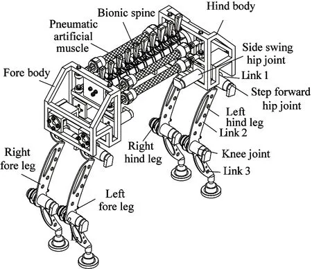
Fig.1 The quadruped robot
2 The bionic spine of musculoskeletal body
The creature spine consists of a number of spine units as shown in Fig.2. The spine unit is composed of vertebral body and intervertebral disc connected with each other as a series of cups and saucers lined up, and the disc is flexible and can provide cushioning.
The bionic spine has 10 DoF passive joints, and itself has no actuator to actuate its motion directly, which is driven by PAMs to achieve creature-like motion.
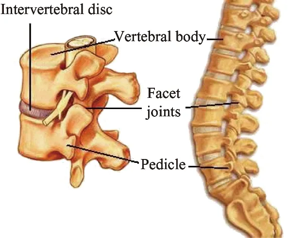
(a) The creature spine
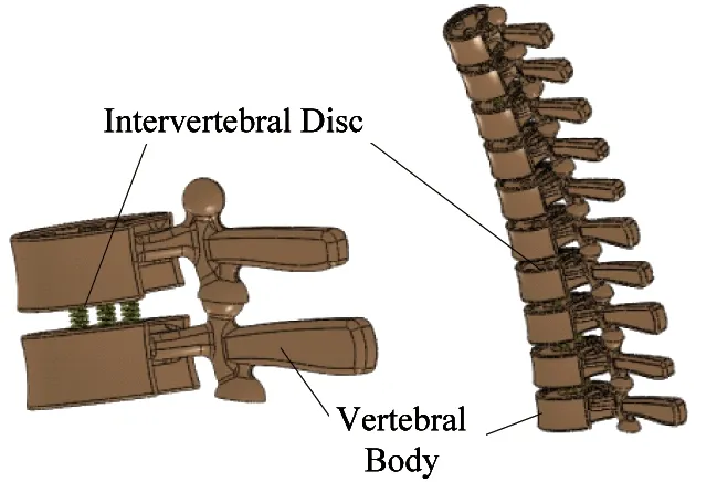
(b) The artificial spine
3 Kinematics analysis
3.1 Spinning gait and turning gait
The stability of the quadruped robot depends on the gait. The quadruped robot needs to work in the rough terrain, so the spinning gait is as important as a straight gait. The spinning gait is different from the turning gait, as shown in Fig.3(a) and (b). The spinning gait is that the robot rotates around the center of the gravity of body (COG) with no rotation radius, which allows the robot to walk in narrow space. The quadruped robot with bionic flexible spine driven by the PAMs can carry out spinning gait.
3.2 Kinematics of flexible body
Kinematics of flexible body is to determine the pose of the hip joint during the body bending.
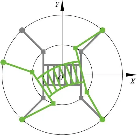
The coordinate systems for kinematics of musculoskeletal body are shown in Fig.4. The thin lines indicate that the body is in initial posture. The thick lines indicate that the body is in the body bending posture.
The body bending angle is θ, so the angle between the fore body and the hind body is 2θ. a and b are the position coordinates of side-swing hip joint in the body coordinate system {B}, and c is the mounting size of PAM in the fore body or hind body. a=280mm, b=80mm, c=88mm.
(a) Spinning gait with body bending
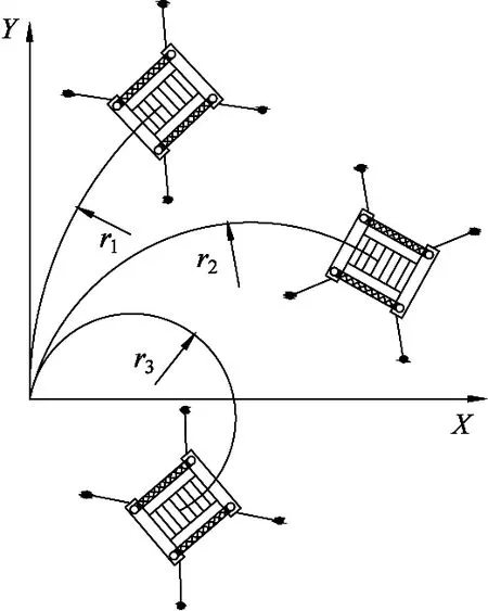
(b) Turning gait
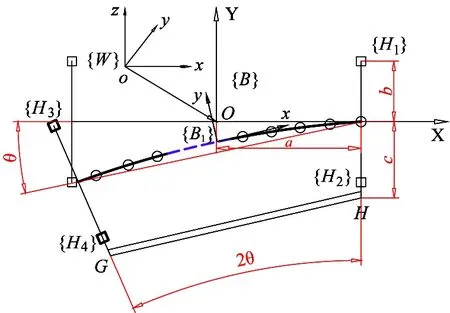
Fig.4 Coordinate frame of bionic body
The kinematics of the quadruped robot can be represented in the world coordinate frame {W}. The body initial coordinate system is {B}, which is located at COG. The body moving coordinate system is {B1}. The coordinate systems of four-side-swing-hip joints are {Hi}(i=1,2,3,4).
The pose of four-side-swing hip joints changes with the body bending. After that, the pose of side-swing hip joints with respect to body can be expressed by the homogeneous transformation matrix as follows:
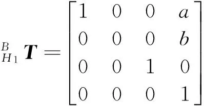
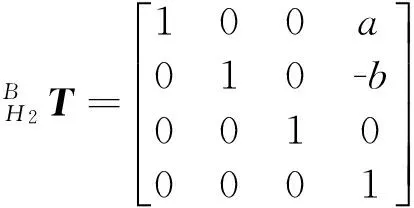


(1)
After body bending the angle θ, the transformation matrix of {B1} with respect to {B} is:
(2)
Firstly, the PAM length should be controlled within a reasonable range in order to achieve the suitable bending angle of the bionic flexible body. Secondly, the body bending angle and leg side swing movement should meet the dynamic stability condition.
When quadruped robot walks with spinning gait and the bionic flexible body bending, the relationship between PAM length and bending angle can be derived according to the geometric relationship.
(3)
where l0=200mm is the initial length of PAM, lh=90mm is the length of the pipe head for connecting the PAM. The PAM length is in inverse proportion to the bending angle.
3.3 Kinematics of leg mechanism
The spinning and the body bending of quadruped robot is shown in Fig.5. The dotted line shows the initial state of feet, and the solid line shows the state after body bending. The kinematics of the quadruped robot can be represented in the world coordinate system {W} or in the body coordinate system.
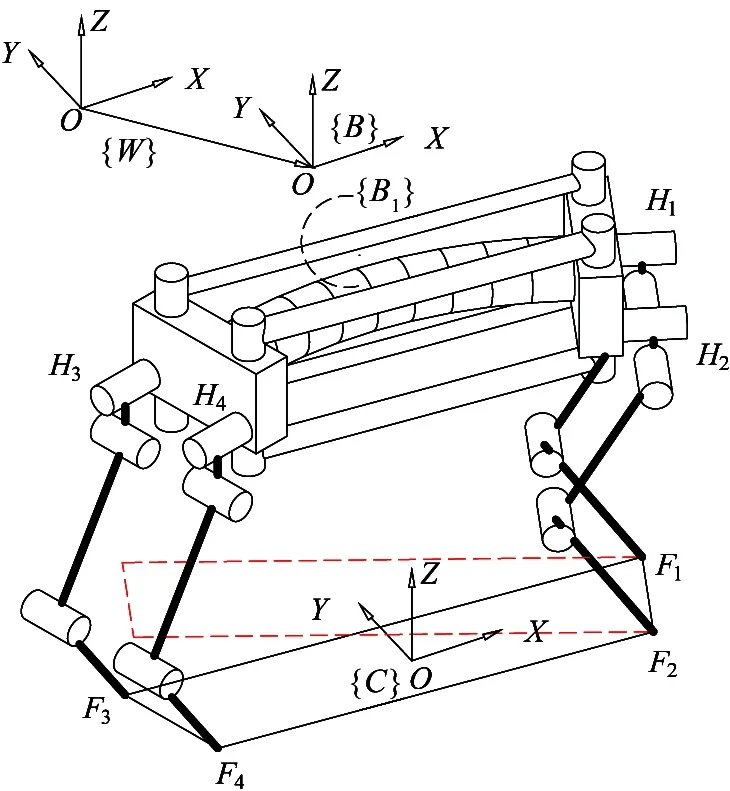
Fig.5 Spinning gait
Each leg has three joints, the joint variable of each leg is defined as:
(4)
where i is the ith leg.
And the joint variable of the quadruped robot can be defined as:
(5)
When quadruped robot walks with spinning gait, after the leg side-swing, the homogeneous transformation matrix of the pose of foot-end {Fi}(i=1,2,3,4) with respect to {Hi}(i=1,2,3,4) can be derived as follows:

(6)
where θi1(i=1,2,3,4) is angular displacement of the side swing hip joint. si=sinθi,ci=cosθi
3.4 Stability analysis of quadruped robot
For the dynamic walking of the robot, the method of zero moment point (ZMP) is generally adopted to evaluate the stability. The dynamically stable walking condition is that the ZMP is always in the polygon formed by the supporting legs. When ZMP exists outside of supporting polygon, the robot will fall down.
The quadruped robot with spinning gait has two legs in supporting phase, the ideal stability condition is that the projection point of COG in the ground plane lies in the diagonal line of the supporting legs. Actually, it does not need to control the projection point of COG in the diagonal line. As long as the projection point of COG is controlled within the stability margin[19], the robot can keep stable. As shown in Fig.6, the vertical distance d is from the projection point of COG to the line of supporting legs.
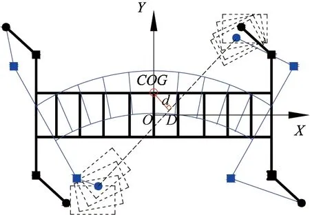
Fig.6 Spinning gait with body bending and leg side-swing
The position of COG can be calculated by Eq.(2), and the position of foot-end can be calculated by Eq.(6). Therefore, there is a relationship among the vertical distance d, body bending angle θ and the angle of leg side-swing θi1(i=1,2,3,4), which can be derived by the stable condition.
4 Experimental analysis
4.1 The controll system
The experiment is conducted to analyze the control algorithm and the bending characteristic of the musculoskeletal body. The control system of the body bending is shown in Fig.7.

Fig.7 The control system
PAMs are highly non-linear pneumatic actuators and their elongation is proportional to the interval pressure[20]. The PAM length should be controlled within the reasonable value according to the need of the body bending angle. The PID controller is designed to control the PAM length, and the error of which is:
e(k)=le-l(k)
(7)
where leis the expected value of the PAM length. l(k) is the real-time length measured by the displacement sensor.
The PAM length error is inputted into PID controller, and voltage output signal is inputted into the proportional valve to adjust the opening size.
4.2 Experiment results and discussion
4.2.1 PAM controlled results
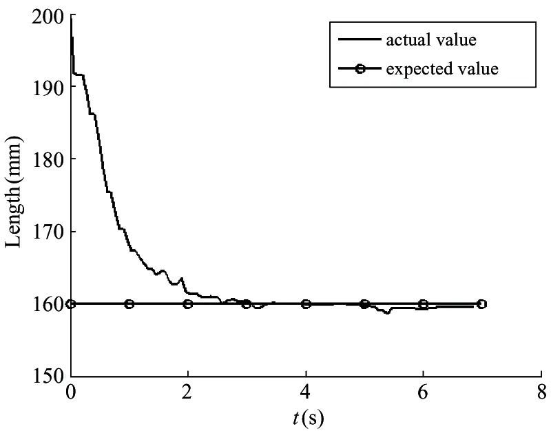
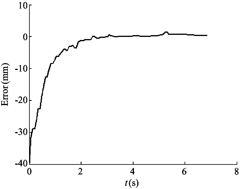
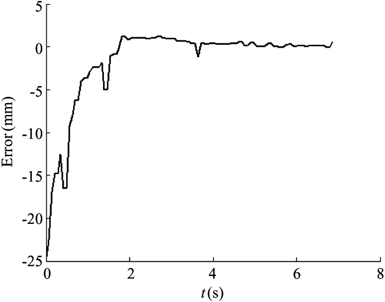
When the expected length of PAM is 160mm, the control results are shown in Fig.8. When the expected length of PAM is 175mm, the control results are shown in Fig.9. Fig.8(a) and Fig.8(b) are PAM length and length error curve, respectively. During 0~2.5s, because of the gas compressibility and nonlinearity, the PAM length changes from 200 to 160mm, then gradually stabilized at 160mm.
The proportional gain kp, integral gain kiand differential gain kdcan be determined. kp=1.5, ki=6, kd=3, and the sampling period is 1.0ms.
(a) The PAM length
(b) The length error
Fig.9(a) and Fig.9(b) are PAM length and length error curve, respectively. During 0~2.5s, because of the gas compressibility and nonlinearity, the PAM length changes from 200 to 175mm, then gradually stabilized at 175mm. kp=1.5, ki=7, kd=2, and the sampling period is 1.0ms.

(a) The PAM length
(b) The length error
4.2.2 Body bending
The experiment system is composed of fore body, hind body, bionic spine, two PAMs, two springs, pressure regulating valve, proportional valve, pressure sensor, displacement sensor and other components. The compressed air is inputted into the components through a φ6mm tube.
The computer Intel Core i5 is used, and the software environment is Labview. PAM model is PAM MAS-20-200N-AA-MC-O, whose initial length l0is 200mm and the initial diameter d0is 20mm. The maximum amount of shrinkage of the PAM is 20% of the initial length.
The proportional valve from Festo company is VPPM-6L-L-1-G18-0L6H-V1P-C1. NI data acquisition card is USB-6212 Bus-Powered M Series Multifunction
DAQ Device. The measuring accuracy of the displacement sensor is ±0.1mm. The pressure sensor is DE1-D10-G2-W18-L-PU-M8, and the measuring accuracy is 2%.
The experiment of the body bending is shown in Fig.10, the PAM length is controlled at 160mm, and the body bending angle reaches 30°.
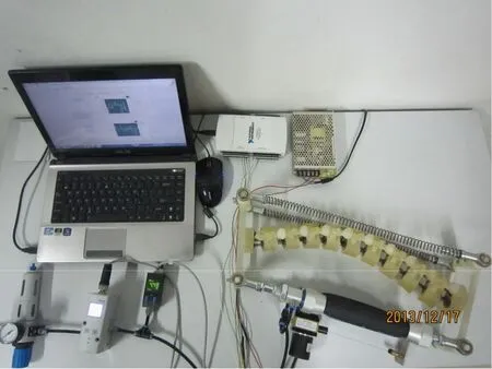
Fig.10 Experiment result of the body bending
4.2.3 Body bending characteristic
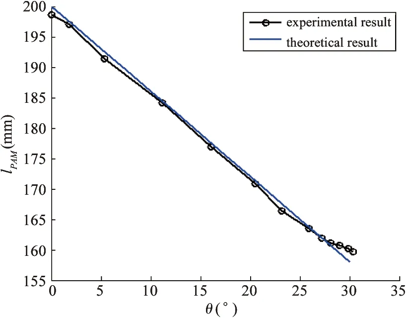
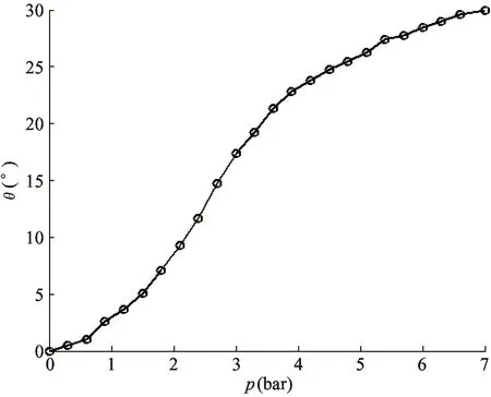
After verifying the PID control algorithm, the bending characteristic of the musculoskeletal body can be tested. The experiment is constructed to determine the relationship between the PAM length lPAMand body bending angle θ, and the relationship between PAM length lPAMand gas pressure p.
The experiment is repeatedly done for several levels of pressures in the range from 0 to 7bar. The experimental data of PAM length, internal gas pressure and body bending angle are measured several times.
The experimental results show the body bending characteristic. The relationship between PAM real-time length and body bending angle is shown in Fig.11(a), which shows the comparison of theoretical and experimental results. The relationship between PAM real-time length and gas pressure is shown in Fig.11(b). The relationship between body bending angle and gas pressure is shown in Fig.11(c).
The experimental results show that:
(1) The biggest bending angle of the musculoskeletal body can reach 30°, which can meet the need of the quadruped robot with spinning gait.
(2) Because the PAM is made of rubber tube and carbon fiber, which has nonlinear characteristic. The PAM length is in approximately inverse proportion to the bending angle.
(3) The PAM length changes with the gas pressure. The PAM length should be precisely controlled in order to achieve the desired bending angle of the musculoskeletal body.
(a) PAM length versus body bending angle

(b) PAM length versus gas pressure
(c) Body bending angle versus gas pressure
5 Conclusions
The quadruped robot should have the mobility and dynamic stability walking in the unstructured environments. A kind of musculoskeletal body driven by PAM for quadruped robot is proposed based on the movement principle of four-legged creature with spinning gait. The coordinated movement between body bending and leg side-swing is analyzed for quadruped robot spinning gait. The bending experiment of musculoskeletal body is conducted to verify the PID control algorithm and the bending characteristic. Studying on the bending characteristic of musculoskeletal body will provide basis for the quadruped robot walking with spinning gait in the unstructured environments.
In the future, there are many problems needing to be studied. PAMs’ highly nonlinear nature causes difficulties in modeling their behavior and designing controller for high-performance positioning systems. The control algorithm should be improved to obtain much quickly response speed and much better control accuracy.
[ 1] Wei J M, Shi Z G, Zhang Q, et al. Gait and stability analysis of a quadruped robot. In: Proceedings of the International Conference on CSIE, Zhengzhou, China, 2011.347-354
[ 2] Cho C H, Min B C, Kim D H. A gait generation for an unlocked joint failure of the quadruped robot with balance weight. In: Proceedings of Advances in Robotics-FIRA Robo World Congress, Incheon, Korea, 2009. 251-261
[ 3] Pouya S, Eckert P, Sproewitz A. Motor control adaptation to changes in robot body dynamics for a complaint quadruped robot. In: Proceedings of the 2nd International Conference on Biomimetic and Biohybrid System, London, UK, 2013. 434-437
[ 4] Sooyeong Yi. Impedance control for body motion of quadruped robot. In: Proceedings of the International Conference on Computer Applications for Security, Control and System Engineering, Jeju Island, Korea, 2012. 190-197
[ 5] Dai Z D. Biomimetics of legged locomotion on unstructured mulit-bar compound:present situation, key technology and future divelopment. Journal of Nanjing University of Aeronautics & Astronautics, 2012, 44(5):621-628 (In Chinese)
[ 6] Park S H, Kim D S, Lee Y J. Discontinuous spinning gait of a quadruped walking robot with waist-joint. In: Proceedings of the International Conference on Intelligent Robots and Systems, 2005. 2744-2749. doi: 10.1109/IROS.2005.1544956
[ 7] Andrikopoulos G, Nikolakopoulos G, Manesis S. A survey on applications of pneumatic artificial muscles. In: Proceedings of the 19th Mediterranean Conference on Control and Automation, Corfu, Greece, 2011. 1439-1446
[ 8] Kingsley D A, Quinn R D, Ritzmann R E. A cocksroach inspired robot with artificial muscles. In: Proceedings of the IEEE/RSJ on the Intelligent Robots and Systems, Beijing, China, 2006. 1837-1842
[ 9] Niiyama R, Kuniyoshi Y. Pneumatic biped with an artificial musculoskeletal system. In: Proceedings of the 4th International Symposium on Adaptive Motion of Animals and Machines, Cleveland, USA, 2008. 80-81
[10] Hosoda K, Takuma T, Nakamoto A. Biped robot design powered by antagonistic pneumatic actuators for multi-modal locomotion. Robotics and Autonomous Systems, 2008. 56: 46-53
[11] Aschenbeck K S, Kern N I, Bachmann R J, et al. Design of a quadruped robot driven by air muscles. Biomedical Robotics and Biomechatronics. In: Proceedins of the 1st IEEE/RAS-EMBS International Conference on BioRob, Pisa, Italy, 2006. 875-880
[12] Miki K, Tsujita K. A study of the effect of structural damping on gait stability in quadrupedal locomotion using a musculoskeletal robot. In: Proceedings of the IEEE/RSJ International Conference on Intelligent Robots and Systems, Vilamoura, Portugal, 2012. 1976-1981
[13] Tsujita K, Miki K. Stability analysis on quadrupedal gaits according to body’s flexibility using musculoskeletal robot. In: Proceedings of the 2011 IEEE International Conference on Robotics and Biomimetics, Phuket, Thailand, 2011. 1609-1614
[14] Tsujita K, Kobayashi T, Masuda T. Feasibility study on stability of gait patterns with changable body stiffness using pneumatic actuators in quadruped robot. Advanced robotics, 2009, 23: 503-520
[15] Deng Q , Wang S G , Xu W, et al. Quasi passive bounding of a quadruped model with articulated spine. Mechanism and Machine Theory, 2012, 52: 232-242
[16] Takuma T, Ikeda M, Masuda T. Facilitating multi-modal locomotion in a quadruped robot utilizing passive oscillation of the spine structure. In: Proceedings of the IEEE/RSJ International Conference on Intelligent Robots ans Systems, Taipei, China, 2010. 4940-4945
[17] Mahmoud A, Okada T, Botelho W T. Estimation and verification of the trajectory forms generated by a legged sliding robot. In: Proceedings of the IEEE International Conference on Robotics and Biomimetics, Guilin, China, 2009. 227-232
[18] Okada T, Hirokawa Y, Sakai T, Shibuya K. Synchronous landing control of a rotating 4-legged robot, PEOPLER, for stable direction change. Climbing and Walking Robots, Part II, 2005. 85-96
[19] Zhang S, Gao J Y, Duan X G, et al. Trot pattern ganeration for quadruped robot based on the ZMP stability margin. In: Proceedings of International Conference on Complex Medical Engineering, Beijing, China, 2013. 608-613
[20] Ganguly S, Garg A, Pasricha A, et al. Control of pneumatic artificial muscle system through experimental modelling. Mechatronics, 2012, 22:1135-1147
Lei Jingtao, born in 1970. She received her Ph.D degree from Beihang University in 2007. She also received her B.S. and M.S. degrees from Henan University of Science and Technology in 1991 and 1996 respectively. Her research interests include the robot mechanisms and robot modular technology.
10.3772/j.issn.1006-6748.2015.03.001
①Supported by the National Natural Science Foundation of China (No. 51375289), Shanghai Municipal National Natural Science Foundation of China (No.13ZR1415500) and Innovation Fund of Shanghai Education Commission (No.13YZ020).
②To whom correspondence should be addressed. E-mail: jtlei2000@163.com Received on June 18, 2014, Yu Huangying
 High Technology Letters2015年3期
- High Technology Letters的其它文章
- Probability density analysis of SINR in massive MIMO systems with matched filter beamformer①
- An energy-saving scheduling scheme for streaming media storage systems①
- Design and analysis on four stage SiGe HBT low noise amplifier①
- Diversity-multiplexing tradeoff of half-duplex multi-input multi-output two-way relay channel with decode-and-forward protocol①
- Edge detection of magnetic tile cracks based on wavelet①
- Probabilistic data association algorithm based on ensemble Kalman filter with observation iterated update①
