Numerical investigations of a tandem stator stage for a small turbo-shaft engine
Wei Wei,Liu Bo
(1.High Speed Aerodynamics Institute of China Aerodynamics Research&Development Center,Mianyang 622661,China;
2.School of Power and Energy,Northwestern Polytechnical University,Xi’an 710072,China)
Numerical investigations of a tandem stator stage for a small turbo-shaft engine
Wei Wei1,*,Liu Bo2
(1.High Speed Aerodynamics Institute of China Aerodynamics Research&Development Center,Mianyang 622661,China;
2.School of Power and Energy,Northwestern Polytechnical University,Xi’an 710072,China)
The highly loaded small compressor is typically characterized by the large adverse pressure gradient,the complex endwall flow and the thick boundary layer,and the layout of the tandem blade is a good way to deal with high loading case according to large amounts of cascade experiments.However,dated design methods can’t meet the needs for the advanced tandem stator and the flow mechanism should to be understood profoundly in small engines.As a result,a redesigned tandem stator is simulated in a highly loaded transonic small compressor with the commercial solver EURANUS.Incidences,deviations and loading splits of tandem blades are inspected to find the three dimensional characteristics.Contrasts are made to capture the flow field benefits between the tandem stator and the original stator.It is found that both the front blade’s deviations and the rear blade’s incidences are not sensitive to the incidence variations,and the front blade undertakes the whole incidence variations nearly.It’s beneficial to distribute the loading uniformly for highly loading stators at the design point in the manner of tandem layout.
tandem stator;tandem cascade;large flow turning;loading split;turbo-shaft engine
0 Introduction
The need for higher power-to-weight gas turbine engines has driven compression systems toward higher pressure ratio,higher efficiency,and less weight by reducing the count of stages and increasing the bladeloading.With the loading increasing,the flow leads to the supersonic or transonic flow in the front stage of compressors,and it will burden the design difficulties of the stators.As for small compressors,the trend weights heavily on the influence of tolerances,clearances,and endwall boundary layers.Some direct difficulties are that the stator has to achieve larger flow turning in smaller passages.
These problems have brought a renewed interest in tandem airfoils where a new boundary layer forms on the rear blade,allowing for great overall loading without large flow separations[1].It originates from the flaps and slats on aircraft to improve lift during taking off and landing.In turbomachinery,tandem airfoils are frequently used as the stator of the final stage such as GE M9001E gas turbine engines[2]and J-79 core compressors[3].Early investigations of tandem configurations are mainly focused on the tandem parameters in the manner of linear cascades,such as the Railly’s lowspeed wind tunnel tests[4]by altering the axial overlap (AO),percent pitch(PP),and stagger angles,and Wu’s moderate speed wind tunnel tests[5]with 24 combinations of tandem parameters.With the aid of NASA,tandem airfoils have been used to design rotors and stators to inspect the potential in compressors and turbines[6-8].Roy and Saha[9-10]use the controlled diffusion airfoils to compare the tandem airfoils with the single airfoil in low-speed tunnel tests.In recent years,M.Hoeger,L.Müller,Li[11-13]had explored the characteristics of the high-turning tandem stator with supercritical(Ma= 0.89)and supersonic(Ma=1.25)inlet Mach numbers for highly loaded fans.Owing to the development of optimization methods[14-15],the optimal tandem cascades could be acquired in numerical optimization ways just considering aerodynamics.
Large amounts of linear tandem cascade experiments show that the tandem airfoil is an effective way to achieve high pressure ratio and hold the low total pressure loss,which is crucial to the development of advanced gas turbine engine.But few studies,from the literature review,are focused on the applications within transonic stages especially for the small engines.Furthermore,the current design methods of tandem blades are still on the basis of rules and experience that are summarized from various linear cascade experiments and 2D numerical results.It is often to be that the middle span of blades works well,while the two endwall regions are worse.Within the small transonic stage,the large adverse pressure gradient,the more complex endwall flow and the thicker boundary layer will make the problem more serious.It is the issue that motivates the flow characteristic investigations of the tandem stator in a highly loaded small turbo-shaft engine.

Fig.1 Geometry illustration of tandem airfoilr图1 串列叶型几何示意图
1 Tandem stator blading
The basic tandem geometry and parameters are depicted in Fig.1.The airfoil geometry can be determined by the parameters of axial overlap(AO),pitch percent (PP)and chord ratio LRA/LFAbetween the front airfoil and the rear airfoil.Different parameters such as the camber ratio(CR),the front airfoil chord etc.can be used to insure the LX,and the CR and stagger angles are used to determine the blade loading split.All tandem configurations have equal chord ratio.
The single airfoils are generated by the camber line and thickness distribution.The camber line is a double arc with the maximum camber point adjusting,so does the maximum thickness point of thickness profiles adjusting with standard cubic polynomial thickness distributions[16].Leading and trailing edges of each airfoil are refined by a circular arc which connects the suction side and pressure side based on the C2 continuity.In this way,the single blade airfoil can be determined and the tandem airfoil can be get by matching the front and rear airfoils reasonably.
The object of the study is a small axial flow transonic compressor extracted from a turbo-shaft engine with a high design total pressure ratio 1.9.Due to the high percent work of shock in rotor tip region,too large exit flow angles of rotor tip profiles make the original stator difficult to fulfill the flow turning angles.Table 1 lists the stator geometrical parameters between the original stator and the tandem stator.Different tandem parametersare be specified for the varying flow conditions across the span such as pitch percent and camber ratio.But the axial overlap is fixed at 0.0 according to the abundant cascade experiments.The final camber ratio and percent pitch distributions are demonstrated in Fig.2 radially.
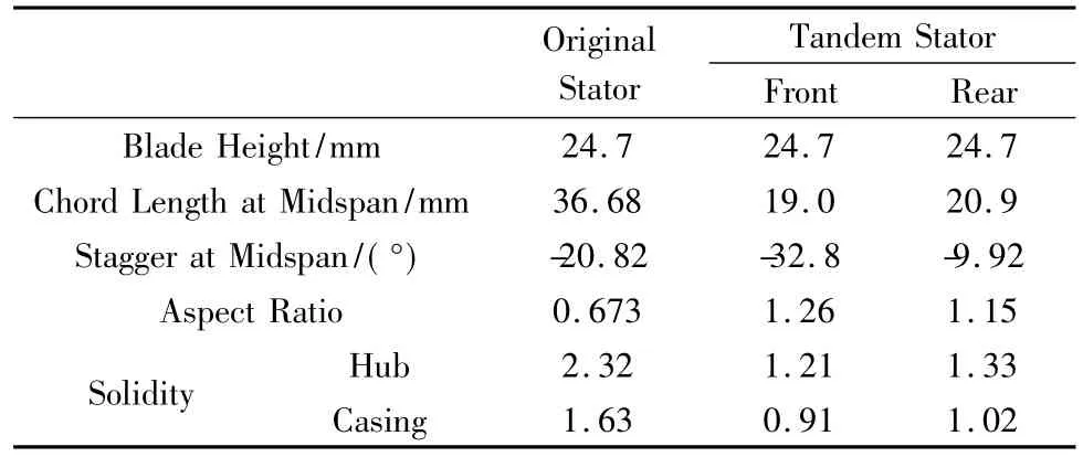
Table 1 Stator geometrical parameters表1 静子几何参数
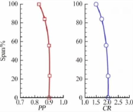
Fig.2 Distributions of PP and CR图2 周向偏距和弯度比径向分布
2 Numerical methods
The Numeca software package is employed to simulate the steady flow of the compressor.Struts,which are behind the stator,are included in the grid model the same as the original turbo-shaft compressor and the detailed analysis is based on the front single stage.
2.1 Grid generation
The grid topologies are generated by IGG/Autogrid.The O4H type grid is adopted to generate the each row.Three levels of grid nodes are chosen to evaluate the effects of grid amount,i.e.0.44,0.55 and 0.65 million for the original stator(case 1-3)and 0.58,0.79,and 0.96 million grid nodes(case 4-6)are for the new tandem stator respectively.The specific grid nodes are shown in Table 2 in details.The distance between the first cell and the solid wall is set 2e-6 meters to meet the y+needs for the Spalart-Allmaras turbulence model[17].Tip clearances of rotor and stator are about 0.5%and 1%average span height respectively.The butterfly grid type with 17 spanwise nodes is employed to generate the spacing mesh.Fig.3 displays the three dimensional(3D)computational grid including the two types of the stator.
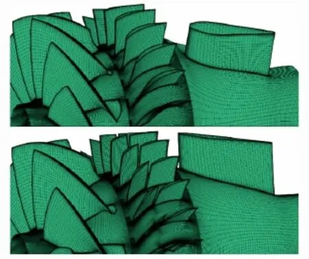
Fig.3 3D computational grids of compressors图3 压气机三维网格图

Table 2 Grid nodes for the validations表2 校验网格分布
2.2 Numerical methods and grid validation
The commercial flow solver EURANUS of Numeca software package is adopted to simulate the 3D viscous flow of the single stage compressor.The central difference scheme is employed to discrete the Reynolds averaged Navier-Stokes(N-S)equation in space,and the four orders explicit Runge-Kutta integration scheme is used for the temporal discretization.The Saplart-Allmaras turbulence model is adopted to compute the flow field.The conservative coupling by pitch-wise row model[18]is employed to provide the conservation of mass flow,momentum and energy through the rotor-stator interface.To accelerate the convergence,full multigrid technique,local time stepping and implicit residual smoothing are employed.
Fig.4 reveals the outlet total pressure ratio distributions with six grid cases as the Table 2 presented.It can be found that the main difference of three profiles focuses on the region near the hub.The amplified picturetakes one more step to reveal the effects of grid nodes.No matter for the original compressor or the new redesign,the differences between case 2 and case 3 or the case 5 and case 6 are not too large,and the differences of the adiabatic efficiency are within the range of 0.01%.In view of the validating results and the 3D calculated amount,the grid nodes of case 2 and 5 are chosen for the 3D steady flow computation for the original and redesigned compressors.
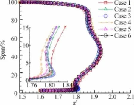
Fig.4 Total pressure ratio distributions after struts图4 支板后总压比径向分布
3 Results and discussions
3.1 Overall performance
The Fig.5 has shown the operating maps of the two single stage compressors at 100%design speed.The design point of the redesigned compressor is determined by the same exit static pressure as the original compressor.It can be seen in Fig.5 that the tandem stator improves the overall performance of the compressor no matter the operating lines or the operating range.The mass flow of the redesigned compressor increases a little by 0.9 percent on the choke conditions.The blockage of these conditions decreases and the temperature rise goes down leading to the isentropic efficiency up obviously.At the design point,the stage isentropic efficiency is about 86%which is nearly 3.5 percent higher than the original stage corresponding to a work coefficient of 0.528.Too large improvement makes us doubt whether or not there is large flow loss in the original stator.On the offdesign conditions close to the surge point,the redesigned compressor keeps good trends of high efficiency and pressure ratio,although the highest efficiency point moves forward.According to the stall margin(SM) equations(1),this margin is also two percents higher than the original.Obviously,the tandem stator shows its potential of higher pressure rise and lower loss in the small compressor.The more detailed understanding of it is in great need of revealing the flow field on all conditions.

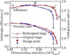
Fig.5 Performance curves of two stages图5 原型级与改型级性能曲线
3.2 Various conditions analysis of tandem stator
As depicted in Fig.5,four conditions are focused on the analysis with signs“A”,“B”,“C”,“D”which represent the near stall condition,the near highest efficiency condition,the design condition and the choke condition respectively.Incidences,deviation angles and tangential loading splits are adopted to get the knowledge of the fluid mechanism.The mass-averaged inlet or exit angles are based on the surface data where locations are 5%chord of each blade away from leading or trailing edges in axial chord.
Fig.6 and Fig.7 demonstrate the incidence angles and deviation angles of front blade across the span.On the design point C,the tandem stator is designed
The same as the original stator with a little negative incidences across the span for the need of enough stability margin.With the conditions close to surge,the incidence profiles change a lot and the range reaches up to 25°at most.Too large incidences will burden the blade loading and induce the boundary layer separation.Especially for the hub on condition A,the severer clearance flow will induced the inlet flow to change the direction and make the incidence more positive.But the limited clearance size determines its influence scope of height.Even the other span is close to its loading limit,there is no stall occurring.Of note are the deviation angles below 0 in Fig.7 on condition A.It is the case that this section,where the flow field data is mass-averaged,just locating in the zone of separation edge.

Fig.6 Front blade incidence angles图6 前叶迎角径向分布
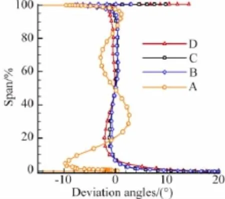
Fig.7 Front blade deviation angles图7 前叶落后角径向分布
In contrast with Fig.6,large incidence variations have a little effect on the deviation angles except for the stall condition.On one hand,the insensitivity of deviation angles near 0°reveals the local fluid field is in relative steady condition with low loss.On the other hand,too large incidences break this relative steady condition and result in flow instability on the front blade near the stall condition.
Fig.8 and Fig.9 represent the rear blade spanwise distributions of incidences and deviations.It can be seen in Fig.8 that the different inlet conditions have a small effect on the incidences of rear blade across the whole span.In contrast with Fig.6,it is not difficult to found that the front blade captured the nearly whole incidence variations.It is the pressure side geometry constraint of front blade that controls the inlet flow direction of rear blade in the absence of large separations.The gap,between the front blade and the rear one,accelerates the internal flow and prevents the passage low energy flow from moving to the rear blade suction side to avoid whole passage blockage.Seen in Fig.9,deviation profiles are in normal range below 80%span on conditions A,B and C.However,a deep“bucket”of the deviation profiles is encountered near the casing on all conditions.Obviously,it is a sign of separations.The main reason is that too large blade camber makes the tip blade section fulfill the overburdened flow turning hardly.The small separation of partial span near tip,the two blades’wakes diffusion and mixing are the main causes of deviation inconformity across span.

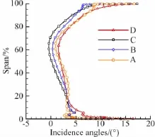
Fig.8 Rear blade incidence angles图8 后叶攻角径向分布
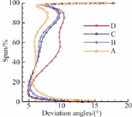
Fig.9 Rear blade deviation angles图9 后叶落后角径向分布
Fig.10 illustrates the loading split(LS)of front blade to rear one on five sections.The loading split is defined by the ratio of tangential forces based on static pressure which provides a measure of“work-split”.
From choke to stall,the loading splits and incidences of the tandem blade are increasing.Too fore(LS>1.0)or aft loading(LS<1.0)will make the design point close to stall or choke like condition A or D.On condition C,a 50/50 split is designed according to the best split in 2D tests[5,11,and13].The CR values are revised near the tip due to the effects of endwall boundary layer.Obviously,The CR profile in Fig.3 differs from the empirical 2D rule especially in the tip region,that a uniform split can be achieved with a CR value near 2.0 on the design point.The bulge of split profiles is a good example for the overburdened fore loading on condition A below 50%,which is an indirect reason for the upcomingstall shown in Fig.7.In other words,the front blade determines the whole stall margin to some extent.Furthermore,loading split is more sensitive to the condition variations among the low span than the tip region.The main causes should owe to the high upstream Ma from 0.96 to 0.83 on 5%span and the larger incidence range shown in Fig.6 from condition C to condition A.A more uniform loading design near the endwalls is in great need of the understanding of flow mechanism in details.

Fig.10 loading split distributions图10 载荷分配比径向分布
3.3 Performance of design point
This part provides insight into the flow field of tandem stator in contrast with the original single stator on design point.Fig.11 displays the surface isentropic Mach number distributions of three typical sections.The isentropic Ma is inversely proportional to static pressure,so the envelope area can reveals the blade loading.As shown in Fig.11,the static pressure rise of the tandem blade is higher than the original stator because of the lower exit Ma without flow separation.
At 5%span,the main improvement locates in the leading edge region where two sharp Ma peaks are on both sides over 1.0 in the original case.The tandem blade eliminates the passage weak shock and decreases the leading edge blockage by the absence of the Ma peak on pressure side.The flow field is compared in the manner of absolute Ma in Fig.12.

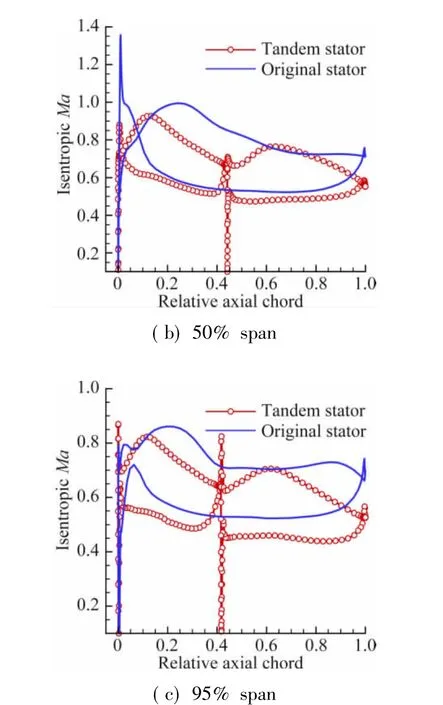
Fig.11 Blade surface isentropic Mach number at design point图11 设计点叶片表面等熵马赫数分布
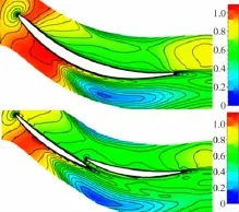
Fig.12 Absolute Ma contours of two stators at 5%span图12 静子5%叶展绝对马赫数云图
In general,the loading profiles with slant trends on the rear half of suction side indicate the increase of suction capacity,while flat distribution near the trailing edge shows signs of impending separation and stall.Obviously,there is not enough loading margin for the rear blade,and it is in good agreement with previous discussion that the stall will start firstly near the hub.
At 50%and 95%span,the tandem blade eliminates the 70% and 40% separations of the original blade respectively.Both the blade loading and the exit static pressure rise are increased.On one hand,the separation of the middle span is the expansion of the tip region shown in Fig.13,and the tandem blade controlsthe separation source and improves the whole flow field of the stator.On the other hand,the convergent gap,between front blade and rear blade,makes the subsonic flow accelerate in it fully to form a local positive pressure gradient.It will protect the flow from separating on remaining suction side.In addition,it is also beneficial for the newly developing boundary layer according to the boundary layer theory[19].In the view of loading distributions,it’s beneficial for blades with a relative uniform profiles among the axial chord.Amounts of past 2D studies,which focus on the relative position AO and PP,are in fact mainly owed to the discussion of gap effects.In 3D flow,the gap geometry also will be a focus in the future numerical optimization.

Fig.13 Absolute Ma contours of two stators on S1,S3 surfaces图13 静子S1、S3面绝对马赫数云图
The absolute Mach number contours are shown in Fig.13 locating in the position 5% chord away from blade trailing edges.Additional attention is paid to dashed curves near casing where the flow field are displayed by blade-to-blade Ma contours with large inlet flow angles nearly-60°.It can be seen that the tandem stator reduces the low speed fluid remarkably.The separating vortex is eliminated and the leakage flow is suppressed to some extent.Due to the separation disappearing,large amount of high entropy flow mixing with the wake is also stopped from diffusing into the passage.In the picture of bottom right corner,gap flow mixes with the front blade wake and suppresses the development all the time until nearly 50%axial chord where it starts to diffuse clearly.But the front blade wake has little effect on the flow field radially shown in the left picture.
The Mass-averaged flow turning Δβ is calculated on the basis of stator’s inlet and outlet spanwise data displayed in Fig.14.Combined with previous analysis,it’s not difficult to find that the Δβ benefits come from the separation disappearing.While,the profiles are nearly same blow 40%span.Therefore,it can be concluded that it’s the high loading capacity of tandem blades that can stop or delay the separation to achieve flow turning benefits.At a moderate loading level such as the region below 40%span,the tandem blade doesn’t show the capacity of larger flow turning.

Fig.14 Flow turnings of two stators across the span图14 串列静子与原静子气流转角沿叶展分布
4 Conclusions
A geometrical redesign is performed on a high turning single stator with tandem blades in the front stage of a small turbo-shaft compressor.Numerical flow characteristic investigations of the tandem stator have been conducted on different conditions and compared to the original stator at the design point.The main conclusions are summarized as follows.
(1)The front blade undertakes the nearly whole incidence variations,and both the deviation angles of the front blade and the incidence angles of the rear blade are not sensitive to the incidence variations.However,it is just the condition that the front blade starts to stall firstly near hub due to the too large loading with high inlet Mach number.
(2)The tandem stator eliminates the original large separations especially for the tip region with more uniform loading distributions.It should be careful of the design of high loading blades with fore loading due to the sharp adverse pressure increasing.The effects of the gap can robust the development of the rear blade’s boundary layer and contribute to the flow field improvement.
(3)The benefits of tandem blades,like flow turnings,will be profound at high loading levels such as the high span region in this paper.It can be concluded that there is a loading critical point where the tandem blade starts to show its advantage with low loss and the wide operating range.
References:
[1] McGlumphy J.Numerical investigation of subsonic axial-flow tandem airfoils for a core compressor rotor[D].Virginia polytechnic institute and state university,2008.
[2] Cyrus V,Rehak K,Polansky J.Unsteady flow in the last stator rows of axial compressor of gas turbine working in coal gasification combined cycle[C]//ASME Turbo Expo 2006,Barcelona,ASME GT2006-90202,2006.
[3] Gostelow J P.Cascade aerodynamics[M].Oxford:Pergamon Press,1984:196-199.
[4] Railly J W,EI-Sarha M F.An investigation of the flow through tandem cascades[J].Proceedings of the Institution of Mechanical Engineers,1965,180(10):66-73.
[5] Guochuan W,Biaonan Z,Bingheng G.Experimental investigation of tandem blade cascades with double circle arc profiles[J].International Journal of Turbo and Jet Engines,1988,5:163-170.
[6] Brent J A,Cheatham J G,Nilsen A W.Single-stage experimental evaluation of tandem airfoil rotor and stator blading for compressors,Part I analysis and design of stages A,B and C[R].NASA CR-120803,1972.
[7] Wood J R,Owen A K,Schumann L F.Performance of a tandem rotor/tandem stator conical flow compressor designed for a pressure ratio of 3.0[R].NASA TP-2034,1982.
[8] Bettner J L.Experimental investigation in an annular cascade sector of highly loaded turbine stator blading,VolumeⅢ.Performance of tandem blade[R].NASA CR-1341,1969.
[9] Roy B,Saha U K.High diffusion cascades for axial flow compressor applications[C]//Proceedings of 15th Canadian Congress of Applied Mechanics,Victoria:University of Victoria,1995:356-363.
[10]Saha U K,Roy B.Compressor cascade performance at low speeds[J].Experimental Thermal and Fluid Science,1997,14:263-276.
[11]Hoeger M,Baier R D.High turning compressor tandem cascade for high subsonic flow,part 1:aerodynamic design[C]//Joint Propulsion conference&Exhibit,San Diego:AIAA 2011-5611.
[13]Qiushi L,Hong W,Sheng Z.Application of tandem cascade to design of fan stator with supersonic inflow[J].Chinese Journal of Aeronautics,2010,23:9-14.
[14]Ju Y,Chinua Z.Multi-objective optimization design method for tandem compressor cascade at design and off design conditions[C]// ASME Turbo Expo 2010,Glasgow,ASME GT2010-22655,2010.
[15] Xiaojia L,Fangfei N.Numerical optimization of aerodynamics of some 3D tandem stators[J].Journal of Aerospace Power,2010,25 (3):577-581.
[16]Forst G R,Hearsey R M,Wennerstrom A J.A computer program for the specification of axial compressor airfoils[R].Ohio:Aerospace Research Laboratories,Wright-Patterson AFB,ARL72-0171,AD756879,1972.
[17]Spalart P R,Allmaras S R.A one-equation turbulence model for aerodynamic flows[C]//30thAerospace Science Meeting&Exhibit,Reno,AIAA-92-0439,1992.
[18]NUMECA.User mannual fine turbo release 8.9[M].Belgium: NUMECA.inc.2011:112-118.
[19] Smith A M O.High-lift aerodynamics[J].Journal of Aircraft.1975,12(6):501-530.
V235.1
Adoi:10.7638/kqdlxxb-2013.0105
0258-1825(2015)04-0493-08
小型涡轴发动机串列静子数值研究
魏 巍1,*,刘 波2
(1.中国空气动力研究与发展中心高速空气动力研究所,四川绵阳 622661; 2.西北工业大学动力与能源学院,陕西西安 710072)
高逆压梯度、复杂端壁流动及厚边界层是高负荷小型压气机的典型特征,大量叶栅试验表明采用叶片串列的布局形式可以很好地解决叶片高负荷的问题。但过时的设计方法不再能满足高负荷串列静子的设计需求,小型发动机中串列叶片的流动机制需要进一步研究。本文采用EURANUS对一高负荷跨声速小型压气机进行了数值模拟,对原始静子进行了改型设计。分析串列静子的迎角、落后角、载荷分配比来发现流动的三维特征,对比流场来甄别串列静子的性能收益。发现前叶的落后角和后叶的气流迎角对静子来流的迎角变化并不敏感,前叶承担了几乎全部来流迎角变化所引起的负荷变化;设计点时以串列的方式更为均匀地分配前后叶的载荷,对级整体性能的提升有益。
串列静子;串列叶栅;大气流转角;载荷分配比;涡轴发动机
2013-11-04;
2014-03-28
魏巍*(1987-),男,重庆万州人,硕士,助理工程师,主要研究方向:叶轮机械气体动力学.E-mail:nwtu@163.com
魏巍,刘波.小型涡轴发动机串列静子数值研究(英文)[J].空气动力学学报,2015,33(4):493-500.
10.7638/kqdlxxb-2013.0105. Wei W,Liu B.Numerical investigations of a tandem stator stage for a small turbo-shaft engine[J].Acta Aerodynamica Sinica,2015,33(4):493-500.

