Kinematic analysis and simulation of sampling machine train of coal sampling at double dynamic
Zhi-xue TO NG,Biao GAO
(School of Mechanical & Electrical Engineering,Xi’an University of Architecture and Technology,Xi’an 710055,China)
1 Introduction
So far,the majority of coal enterprises have two ways to sample the coal in the train mechanically.When the train is stationary,the sampling head will be inserted into the compartment.This approach has the advantage that it could achieve full cross-section sample,but the drawback is that each section of the sampled train must be stationary,which leads to decrease the sampling efficiency significantly [1].In order to improve the sampling efficiency,there exists an another way.When the train is traveling,the sampling head could be extended into the compartment(for double dynamic sampling).This sampling method could reduce the time of trainspause,and the sampling efficiency could be significantly improved.However,due to the technical limitations,the sampling head in this method can only be inserted into the surface of the coal samples,and it can not achieve full section sampling.Therefore,it is difficult to ensure the representative of the collected samples[2].It becomes a difficult problem that how to realize the sampling machine and double acting under the implementation of full section sampling.
To solve this problem,this article studies the composition of the sampling machine,the agency conducted a forward and inverse kinematics analysis.Then,the hydraulic cylinder,motor sport curve and trajectory of sampling head are obtained by the simulations.Thus,we provided a theoretical basis for the control sampling machine to complete the entire section of the sample in the double-action case.
2 Sampling machine modeling
The sampling machine model is shown in Fig.1[3].The sampling arm consists of a big arm,an arm,a forearm and a sampling head.Relative to the base,the big arm could swing around the hinge point under the push of cylinder,and the arm could swing around the big arm under the drive of its cylinder,the forearm will swing around the arm under the drive of the cylinder on the big arm,and the sampling head will swing around the forearm under the push of the rotary cylinder.The sampling arm can be driven by the motor rotation relative to the base.
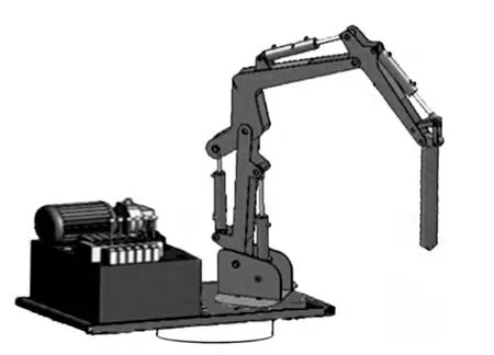
Fig.1 Sampling machine model
3 Kinematics analysis
The whole mechanism of sampling machine has 5 degrees of freedom,we can control the rotary motor and each hydraulic cylinder,which makes the sampling machine could complete the complex sampling action[4].In order to control the motion of sampler,we need to carry on a kinematics analysis to obtain kinematic curve of the hydraulic cylinders and the motor.So as to facilitate the analysis,the simplification of 3D model of Fig.1 is shown in Fig.2.
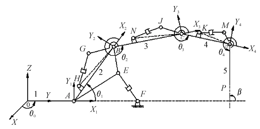
Fig.2 The simplification of the sampling machine
3.1 Forward kinematics analysis
If each link parameters and the joint variables are all known,a forward kinematics problem could be solved to obtain the sampling space position of the head[5].
D-H coordinate system is established in the sampling machine movement diagram which is shown in Fig.2.Once the analysis of diagram 1 is finished,one could obtain the parameters of the sampler and the range of joint variables,as shown in Table 1.
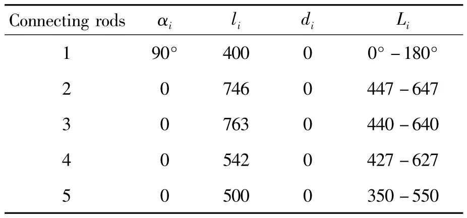
Table 1 The parameters of the sampler and the range of joint variables
liis the center distance between the two hinge of ith component;diis the offset of the adjacent rods;αiis the twist angle;Liis the range of rotation angles for the motor and the range of length of the boom cylinder(L2),the arm cylinder (L3),the forearm cylinder(L4)and the rotary cylinder(L5)for the rod 1,2,3,4 and 5,respectively.
Because the study sample machine has spatial structure,sampling arm is composed by joints and connecting rods,so the two coordinate transformation matrix between adjacent rods could be obtained as follows[6]:

Combined with Table 1 the homogeneous transformation matrix between the adjacent rods,the following could be obtained:
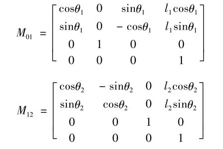
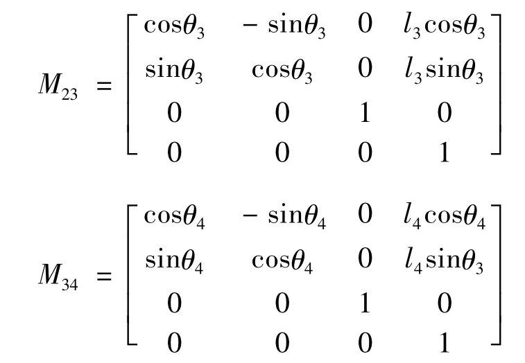
Relative to the base coordinate system,the homogeneous transformation matrix (M04)of the sampling arm (D)could be obtained as follows:

This is the forward kinematics equation of the sampling machine[7].
3.2 Solving inverse kinematics
Inverse kinematics solution is a process that the variable of each joint in the case could be obtained if the space position of sampling head is known[8].
Relative to the base coordinate system,the position matrix for the end of the sampling machine is shown as follows:

Compared with the formula (1)and (2),a set of nonlinear equations can be obtained,as shown in Eq.(3).
In which c1=cosθ1,c2=cosθ2,c3=cosθ3,c4=cosθ4,s1=sinθ1,s2=sinθ2,s3=sinθ3,s4=sinθ4.
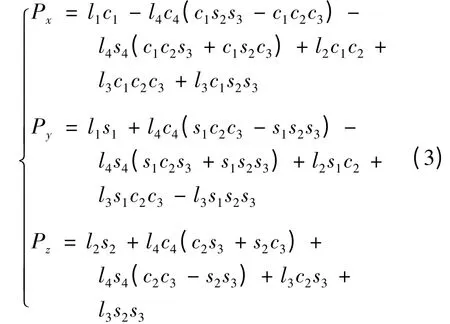
In the actual sampling process,generally sampling head will move along a linear at a constant speed to complete the full section sampling.This paper studies the vertical sampling while the train moves at a constant speed,it requires sampling head and the train must be kept synchronized,the trajectory of sampling head is a space oblique line.Combined with Table 1 and Fig.2,the trajectory could be planned out as a space oblique line parallel to XOZ plane [9].The parameter equations of this skew lines in the base coordinate could be shown in equation (4):

Px∈[-700,700].
That is to say,if we substitute Px,Pyand Pzof each point which satisfy the equation (4)into equation group (3),we can solve the variables of the joint.Since equation(3)has three equations and four unknowns,so there is no definite solution.In order to obtain the solution,combined with the actual situation we assume that the position of the big arm is unchanged,so θ2is a constant (its value is 80 degrees by experience).Therefore,the equation (3)could have unique solutions[10].
In addition,β is the angle between x1and the sampling head in Fig.2,we should make sure the sample is vertical sampling at a constant speed,so β=π/2.The angle θ5between sampling head and forearms could be obtained as follows[11]:

In order to meet the needs of practical control,the variables of joint must be converted into the length of hydraulic cylinder and the change of the motor rotation.According to the geometric relationship as shown in Fig.2,the relation between the length of hydraulic cylinder Liand joint angle θicould be obtained as follows[12]:

∠BAE,∠HBA,∠NCB,∠CDK is β1,β2,β3,β4respectively.h is the length of arm and AB=h1,BC=h2,CD=h3,DP=h4,both of themare fixed value.
4 Simulation
According to equations (3),(4),(5)and (6),we could simulate the motion of sampler by using Matlab,and then the displacement curve of hydraulic cylinder and the angle of the motor rotation could be obtained when it moves at a constant speed as shown in Fig.3,the trajectory of sampling head is shown in Fig.4[13].
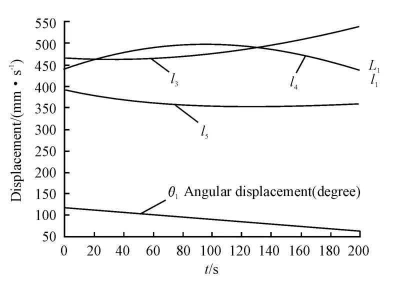
Fig.3 The displacement curve of hydraulic cylinder and the angle of the motor rotation
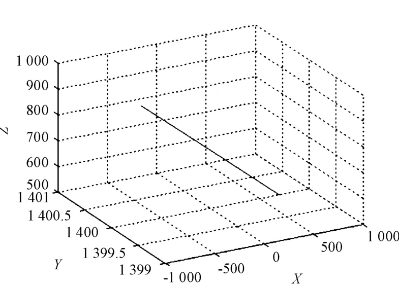
Fig.4 The trajectory of sampling head
According to the fitting and derivation of the curve shown in Fig.3,we get the curves which could describe the speed of the hydraulic cylinder and the angular velocity of the motor,as shown in Fig.5.
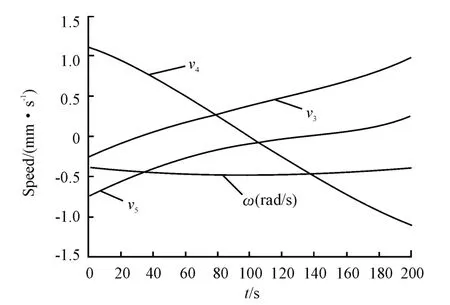
Fig.5 The speed of the hydraulic cylinder and the angular velocity of the motor
According to the Fig.3 and 4,within the predetermined time,the change of sampling’s coordinate is uniform,movement is smooth,the change of the hydraulic cylinder’s length and motor’s rotation angle are within the range as shown in Table 1.All of them proved that the parameters of the connecting rod are reasonable,trajectory planning is also very good and it has reached the requirement of sampler motion control[14].
Fig.5 shows that in the process of movement,the speed of hydraulic cylinder and motor could change gradually,the curve of position is smooth,and it proves the parameters of each connecting rods are designed very well.On the other hand,if we send the simulation results of Matlab to the controller,the motion controlled sampling machine can achieve the full section sampling in the double-action situations.
5 Conclusions
This article conducted the kinematic analysis of sampler based on the trajectory of the train coal sampling machine control requirements,and it proposed to solve the nonlinear equations by using Matlab method for the inverse kinematics of articulated arm problems,and then it obtained sampling head trajectory and hydraulic cylinders and motors versus time through the Matlab simulations.
Acknowledgements
This paper is supported by The Shaanxi Province Industrial Research Projects (2012K10-10),2015GY068 project categories:Industrial Technology Research of Shaanxi Province project name:The key technology research on coal sampling manipulator full face high speed sampling.
[1]ZHU P,et al.Study on the fully automatic sampler for coal trucks[J].COAL PROCESSING & COMPREHENSIVE UTILIZATION,2011(3):21-25
[2]TONG Z X,SHI L C,ZHANG L G.Study on track control to multiple degrees of freedom mechanical arm of the sampling machine for coal at railway carriage[J].JOURNAL OF MACHINE DESIGN,2012,29(9):81-84.
[3]LIANG C.Variable-parametered simulation analysis of four-bar linkagesof hydraulic supports based on SolidWorks[J].Mining machinery,2011,39(3):18-20.
[4]ZHANG D D.Kinematics Analysis and Simulation of High Voltage Special Operation Manipulator[J].JOURNAL OF MECHANICAL TRANSMISSION,2012,36(9):62-66.
[5]WANG Z Z,ZHANG J,JI H Y,et al.Kinematics analysis and simulation for auto-materiel feeding manipulator[J].Machinery Design&Manufacture,2012,42(5):244-246.
[6]ZHOU W D.Study on the design and motion of light excavator[J].MANUFACTURING AUTOMATION,2010,32(7):166-168.
[7]CUI J,ZHANG Y C.Kinematics analysis for a 6-DOF manipulator[J].Mechanics,2009,36(11):16-19.
[8]LI B,YAN J,ZENG Y H,et al.Kinematics modeling and analysis of excavator working device[J].JOURNAL OF MACHINE DESIGN,2011,28(10):7-10.
[9]WANG Z X,FAN W X,ZHANG B C,et al.Kinematical analysis and simulation of industrial robot based on Matlab[J].Journal of Mechanical & Electrical Engineering,2012,29(1):33-37.
[10]CHEN Y,ZOU X J,XU D F,et al.Mechanism design and kinematics simulation of litchi picking manipulator[J].JOURNAL OF MACHINE DESIGN,2010,27(5):31-34.
[11]OSTAPSKI W.Analysis of the stress state in the harmonicdrive enerator-flexspline system in relation to selected structuralarameters and manufacturing deviations[J].Technical Sciences,2010,58(4):683-698.
[12]LI Z H,LIAO X P,LIN Y Z,et al.The kinematics analysis and simulation for 6R joint painting spraying robot[J].Machinery Design & Manufacture,2010,4(4):176-178.
[13]LUO J J,HUG Q.Study on the Simulation of Robot Motion Based on MATLAB[J].Journal of Xiamen University:Natural Science,2005,9(5):640-644.
[14]WANG B Z,HE Q H,HAO P,et al.Optimization research on bucket connecting rod machnism of excavation robot[J].Journal of Machine Design,2010,2(2):30-32.

