掺锡氧化铟导电玻璃的表面改性及其性能研究
陈首部
(中南民族大学 电子信息工程学院,武汉 430074)
掺锡氧化铟(In2O3:Sn)作为一种非常重要的透明导电氧化物半导体材料,它不仅具有稳定的化学性质,而且具有优良的导电性能和透光性能,因此被广泛应用于太阳能电池、电致发光、液晶显示、传感器以及激光器等光电子器件领域[1-10].对于聚合物太阳能电池和电致发光器件,其典型结构为“三明治式”的夹心结构,即聚合物功能层被夹在上、下两个电极之间,其中器件负极常常选用低功函的金属材料,而正极则大多采用透明的In2O3:Sn导电玻璃[1-4].众所周知,由于In2O3:Sn属于非化学计量学化合物,沉积条件、后处理工艺和清洗方法等因素都将明显影响其表面性质[6,7],进而对它与功能层之间的界面特性及其器件性能产生较大的影响,因此人们对In2O3:Sn薄膜表面改性进行了比较广泛的研究[11-21].但是这些研究主要集中在In2O3:Sn薄膜的功函数、载流子注入等电学性质方面,而对于其表面湿润性能、表面能等物理化学性质的研究则很少报道.
本文采用不同方法对In2O3:Sn导电玻璃进行表面改性,通过原子力显微镜(AFM)和接触角测试,研究了改性方法对In2O3:Sn导电玻璃表面形貎和湿润性能的影响;同时通过调和平均方法计算,定量地讨论了改性方法对样品表面能参数和表面极性度的影响.
1 实验过程
本实验选用南玻公司生产的In2O3:Sn导电玻璃作为研究对象,样品尺寸为3 cm×3 cm方块,为了研究改性方法对导电玻璃性能的影响,实验采用下列方法对其进行表面处理:(1)溶剂超声处理―依次采用洗涤剂溶液、无水酒精和去离子水对导电玻璃各超声清洗约10 min,并用高纯氮气吹干;(2)H2SO4溶液浸泡―先用洗涤剂溶液和无水酒精对导电玻璃各超声清洗约10 min,再用H2SO4溶液浸泡约5 min,最后采用去离子水超声清洗10 min,并用高纯氮气吹干;(3)NaOH溶液处理―首先用洗涤剂溶液和无水酒精对导电玻璃各超声清洗约10 min,然后用NaOH溶液浸泡约10 min,最后采用去离子水超声清洗约10 min,并用高纯氮气吹干.本实验中将经过溶剂超声处理、H2SO4溶液浸泡和NaOH溶液处理的In2O3:Sn导电玻璃分别标记为1#、2#和3#样品.通过原子力显微镜(AFM)表征样品的表面形貎,分别选用蒸馏水和二碘甲烷作为测试液体来测量样品表面的接触角,并根据调和平均法计算各样品的表面能、表面能分量和表面极性度,实验所用测试液体的表面张力参数[22,23]如表1所示.

表1 测试液体的表面张力参数 mJ/m2
2 表面能计算方法
表面张力(或表面能)是产生单位面积新表面所需的可逆功,它是液体(或固体)重要的表面物理参数之一,其产生根源是物质分子间的相互作用力.一般而言,液体的表面张力可以直接测定,而固体的表面能则只能采用间接方法来计算.
根据极性成分理论,Wu[22]利用半连续模型中能量可加性概念,并假定分子之间的作用能是由非极性分量和极性分量两部分所组成,其中非极性分量是色散作用对表面能的贡献;而极性分量则是静电力、诱导力以及氢键等作用对表面能的贡献.如图1所示,当液体浸润固体并达到平衡状态时,由Young方程[22,23]可得:
γS=γSL+γLcosθ,
(1)
(1)式中,γS为固体的表面能,γL为液体的表面张力,θ为液体在固体表面上的接触角,γSL为固体与液体(固-液)之间的界面能.根据Dupré方程[22,23],固-液之间的粘结功(Wa)可以表示为:
Wa=γS+γL-γSL.
(2)
联合公式(1)和(2)可得,粘结功Ws与γL、θ之间的关系为:
Wa=γL(1+cosθ),
(3)
由公式(3)看出:固-液之间的粘结功Wa与接触角θ密切相关,当γL一定时,θ越小,则湿润性越好,Wa越大;θ越大,则湿润性越差,Wa越小.因此,常用接触角θ的大小来度量湿润性能和粘结强度.
根据调和平均方程原理[22,23],固-液之间的粘结功Wa又可以表示为:
(4)
由公式(3)和(4),可以得到调和平均法计算固体表面能的方程式为:
(5)
(6)
(7)
分别计算出该固体的总表面能γS和表面极性度χp.
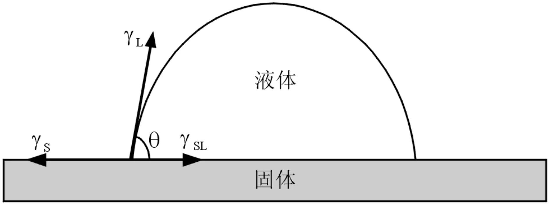
图1 液体在固体表面上的示意图Fig.1 Side view of a liquid drop deposited onto a solid surface
3 结果与讨论
图2为经过不同方法处理后In2O3:Sn导电玻璃样品表面的AFM形貌图,由图可见,经过表面改性后,导电玻璃表面形貌存在着比较明显的差异:1#样品表面显示出无序状,表面颗粒排列杂乱无章;而2#样品和3#样品的表面则显示为比较规整,只是2#样品表面的颗粒尺寸比3#样品稍小些.表2列出了所有In2O3:Sn导电玻璃样品的平均粗糙度(Ra)、峰谷粗糙度(Rpv)和颗粒半径(Rg)数据,从表中可以看出,1#样品的Rg值变化范围很大,达到30~136 nm,这很可能是由于随机粘附的污染物所导致的.与1#样品相比,2#样品和3#样品表面的Ra、Rpv和Rg数值都有不同程度的减小.In2O3:Sn导电玻璃样品表面平均粗糙度Ra的降低和表面颗粒半径Rg的减小,有利于增加In2O3:Sn导电玻璃与功能薄膜之间的有效接触面积,因此对增大它们之间的附着是非常重要的[24--27].
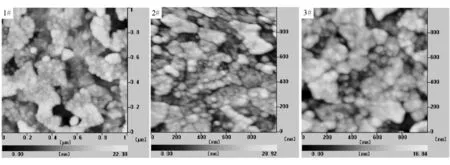
图2 处理后样品表面的AFM图Fig.2 AFM micrographs of the treated samples

样品Ra/nmRpv/nmRg/nm1#3.12530~1362#2.41330~353#2.51432~43
图3和图4为经过不同方法处理后In2O3:Sn导电玻璃样品表面上的接触角数据,其中θ1为蒸馏水在样品表面上的接触角,θ2为二碘甲烷在样品表面上的接触角.由图可以看出,对于1#、2#和3#样品,θ1分别为64.5°、41.3°和35.9°,而θ2分别为39.8°,33.7°的32.2°,结果表明θ1的变化范围较宽、θ2的变化范围较窄,并且它们都具有类似的变化趋势,特别是3#样品的θ1和θ2同时具有最小值.经过NaOH溶液处理后,In2O3:Sn导电玻璃表面上接触角明显减小,说明了该表面改性方法能够有效提高In2O3:Sn导电玻璃表面的亲水性,并改善其表面湿润性能.

图3 水在样品表面上的接触角Fig.3 Water contact angle of the treated samples

图4 二碘甲烷在样品表面上接触角Fig.4 Diiodomethane contact angle of the treated samples

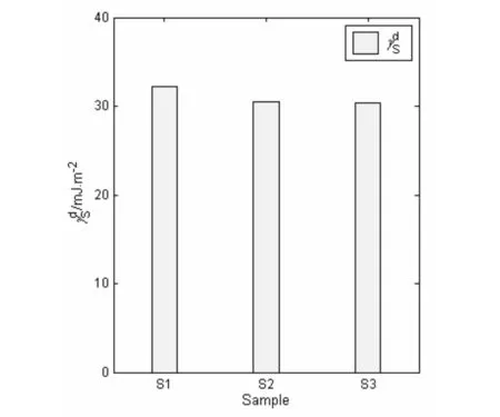
图5 处理后样品表面自由能的非极性分量Fig.5 Nonpolar component of the treated samples

图6 处理后样品表面自由能的极性分量Fig.6 Polar component of the treated samples
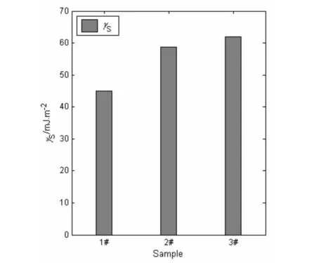
图7 处理后样品的表面自由能Fig.7 Surface energy of the treated samples
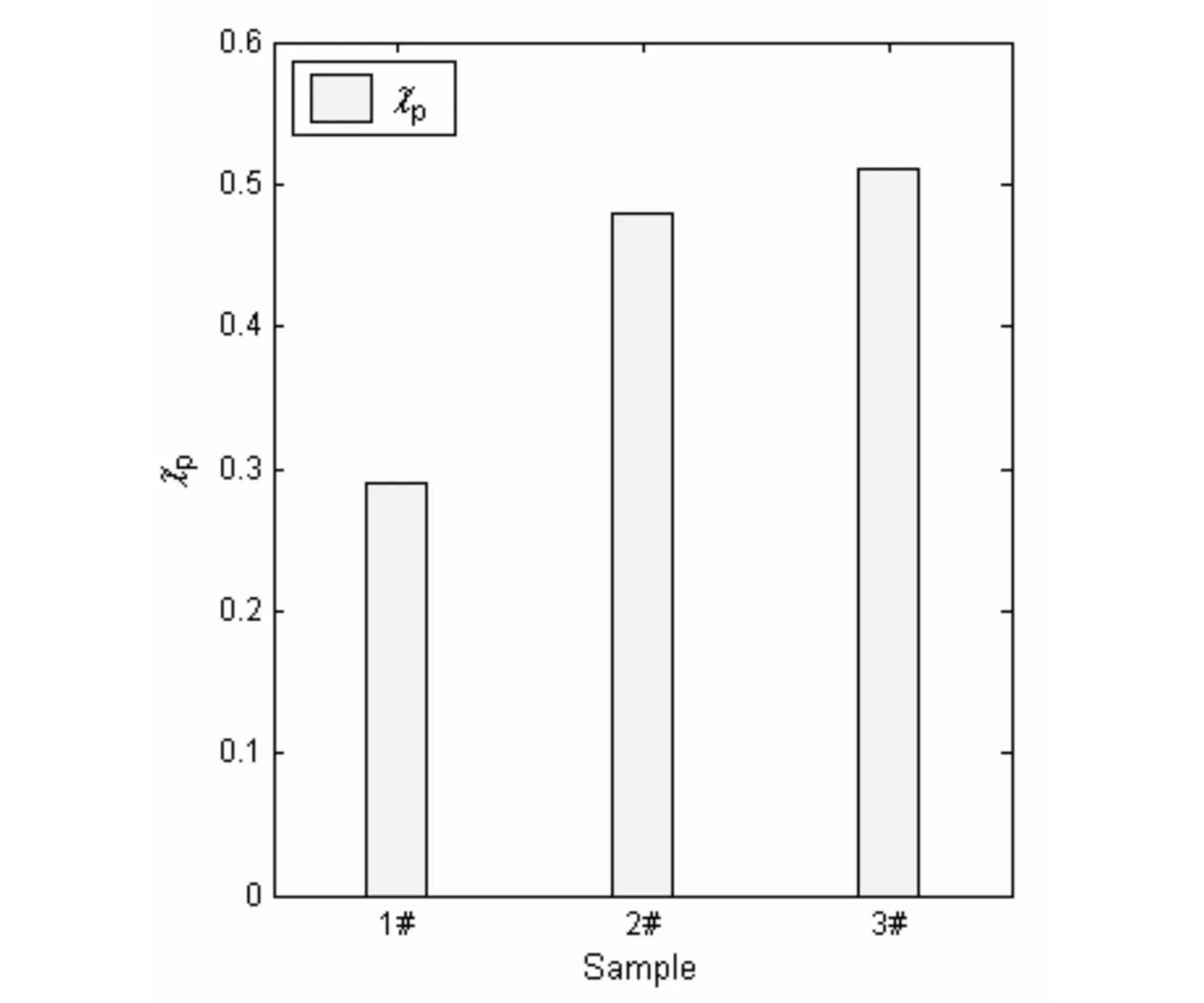
图8 处理后样品的表面极性度Fig.8 Surface polarity of the treated samples

4 结语
采用溶剂超声、H2SO4溶液浸泡和NaOH溶液处理分别对In2O3:Sn导电玻璃进行表面改性,通过AFM和接触角测试,研究了改性方法对导电玻璃表面形貎和润湿性质的影响.结果表明,改性方法对导电玻璃表面性能具有不同程度的影响,其中H2SO4溶液浸泡和NaOH溶液处理更有效地降低了表面粗糙度和颗粒尺寸,优化了导电玻璃的表面形貎.同时基于测量的接触角,采用调和平均法研究了改性处理对导电玻璃表面能和表面极性度的影响,结果显示,In2O3:Sn导电玻璃的表面能参数与改性方法密切相关,与溶剂超声处理相比,H2SO4溶液浸泡和NaOH溶液处理具有更高的表面能和表面极性度,并且其表面能的变化主要取决于表面能极性分量的变化.
参 考 文 献
[1] Park Y S, Kim E, Hong B, et al. Characteristics of ITO films with oxygen plasma treatment for thin film solar cell applications[J]. Materials Research Bulletin, 2013, 48(12): 5115-5120.
[2] Tang C W, VanSlyke S A. Organic electroluminescent diodes[J]. Applied Physics Letters, 1987, 51(12): 913-915.
[3] Kido J, Kimura M, Nagai K. Multilayer white light-emitting organic electroluminescent device [J]. Science, 1995, 267(5202): 1332-1334.
[4] Burroughes J H, Bradly D D C, Brown A R, et al. Light-emitting diodes based on conjugated polymer[J]. Nature, 1990, 347(6293): 539-541.
[5] Zhong Z, Zhong Y, Liu C, et al. Study on the surface wetting properties of treated indium-tin-oxide anodes for polymer electroluminescent devices[J]. Physica Status Solidi A-Applications and Materials Science, 2003, 198(1): 197-203.
[6] Brabec C J, Sariciftci N S, Hummelen J C. Plastic solar cells[J]. Advanced Functional Materials, 2001, 11(1): 15-26.
[7] Kim Y S, Park Y C, Ansari S G, et al. Effect of substrate temperature on the bonded states of indium tin oxide thin films deposited by plasma enhanced chemical vapor deposition[J]. Thin Solid Films, 2003, 426(2): 124-131.
[8] Zhong Z Y, Jiang Y D. The surface properties of treated ITO substrates effect on the performance of OLEDs[J]. The European Physical Journal-Applied Physics, 2006, 34(3): 173-177.
[9] Wrzesińska H, Ilka L, Wawer D, et al. Investigation of indium tin oxide (ITO) films for the VCSEL laser with dielectric Bragg reflectors[J]. Physica Status Solidi C-Current Topics in Solid State Physics, 2004, 1(2): 396-400.
[10] Zhang J, Hu J, Zhu Z Q, et al. Quartz crystal microbalance coated with sol-gel-derived indium-tin oxide thin films as gas sensor for NO detection[J]. Colloids and Surfaces A-Physicochemical and Engineering Aspects, 2004, 236(1-3): 23-30.
[11] 钟志有. 有机LED器件结构对其内部电场和电荷分布的影响[J]. 中南民族大学学报:自然科学版, 2009, 28(3): 73-78.
[12] Zhong Z Y, Jiang Y D. Surface treatments of indium-tin oxide substrates for polymer electroluminescent device[J]. Physica Status Solidi A-Applications and Materials Science, 2006, 203(15): 3882-3892.
[13] Tak Y H, Kim K B, Park H G, et al. Criteria for ITO (indium tin-oxide) thin film as the bottom electrode of an organic light emitting diode[J]. Thin Solid Films, 2002, 411(1): 12-16.
[14] Jung S, Park N G, Kwak M Y, et al. Surface treatment effects of indium-tin oxide in organic light-emitting diodes[J]. Optical Materials, 2002, 21(2): 235-241.
[15] Kim J S, Ho P K H, Thomas D S, et al. X-ray photoelectron spectroscopy of surface-treated indium-tin oxide thin films[J]. Chemical Physics Letters, 1999, 315(5-6): 307-312.
[16] Kim J S, Cacialli F, Cole A, et al. Increase of carrier density and reduction of Hall mobilities in oxygen-plasma treated indium-tin-oxide anodes [J]. Applied Physics Letters, 1999, 75(1): 19-21.
[17] Choi B, Yoon H, Lee H H. Surface treatment of indium tin oxide by SF6 plasma for organic light-emitting diodes [J]. Applied Physics Letters, 2000, 76(4): 412-414.
[18] So S K, Choi W K, Cheng C H, et al. Surface preparation and characterization of indiumtin oxide substrates for organic electroluminescent devices [J]. Applied Physics A-Materials Science & Processing, 1999, 68(4): 447-450.
[19] Chan I-M, Cheng W-C, Hong F C. Enhanced performance of organic light-emitting devices by atmospheric plasma treatment of indium tin oxide surfaces[J]. Applied Physics Letters, 2002, 80(1): 13-15.
[20] Qiu Y, Zhang D Q, Wang L D, et al. Performance improvement of organic light emitting diode by low energy ion beam treatment of the indium tin oxide surface[J]. Synthetic Metals, 2002, 125(3): 415-1418.
[21] Nguyen T P, Le Rendu P, Dinh N N, et al. Thermal and chemical treatment of ITO substrates for improvement of OLED performance[J]. Synthetic Metals, 2003, 138(1-2) 229-232.
[22] Wu S. Polymer interface and adhesion[M]. New York: Marcel Dekker, 1982.
[23] Kaelble D H. Physical chemistry of adhesion[M]. New York: Wiley, 1971.
[24] Wu C C, Wu C I, Sturm J C, et al. Surface modification of indium tin oxide by plasma treatment: an effective method to improve the efficiency, brightness, and reliability of organic light emitting devices[J]. Applied Physics Letters, 1997, 70(11): 1348-1350.
[25] Nüesch F, Rothberg L J, Forsythe E W, et al. A photoelectron spectroscopy study on the indium tin oxide treatment by acids and bases[J]. Applied Physics Letters, 1999, 74(6): 880-882.
[26] Sugiyama K, Ishii H, Ouchi K. Dependence of indium-tin-oxide work function on surface cleaning method as studied by ultraviolet and x-ray photoemission spectroscopies[J]. Journal of Applied Physics, 2000, 87(1): 295-298.
[27] Ishii M, Mori T, Fujikawa H, et al. Improvement of organic electroluminescent device performance by in situ plasma treatment of indium-tin-oxide surface[J]. Journal of Luminescence, 2000, 87-89: 1165-1167.
[28] Zhong Z Y, Jiang Y D. Surface treatments of indium-tin oxide substrates for polymer electroluminescent devices[J]. Physica Status Solidi A-Applications and Materials Science, 2006, 203(15): 3882-3892.
[29] Abderrahmen A, Romdhane F F, Ouada H B, et al. Indium-tin oxide surface treatments: effects on the performance of liquid crystal devices[J]. Materials Science and Engineering C-Materials for Biological Applications, 2006, 26(2-3): 538-541.
[30] You Z Z, Dong J Y. Effect of oxygen plasma treatment on the surface properties of tin-doped indium oxide substrates for polymer LEDs[J]. Journal of Colloid and Interface Science, 2006, 300(2): 697-703.
[31] Chan I-M, Cheng W-C, Hong F C. Enhanced performance of organic light-emitting devices by atmospheric plasma treatment of indium tin oxide surfaces[J]. Applied Physics Letters, 2002, 80(1): 13-15.
[32] Qiu Y, Zhang D Q, Wang L D, et al. Performance improvement of organic light emitting diode by low energy ion beam treatment of the indium tin oxide surface[J]. Synthetic Metals, 2002, 125(3): 415-418.
[33] Nguyen T P, Le Rendu P, Dinh N N, et al. Thermal and chemical treatment of ITO substrates for improvement of OLED performance[J]. Synthetic Metals, 2003, 138(1-2): 229-232.

