Equivalent pipe algorithm for metal spiral casing and its application in hydraulic transient computation based on equiangular spiral model*
PENG Xiao-dong (彭小东)
State Key Laboratory of Hydraulics and Mountain River Engineering, Sichuan University, Chengdu 610065, China, E-mail: mypxiaod@126.com
YANG Zhao-hui (杨朝晖)
Department of Water Resources of Guizhou Province, Guiyang 550002, China
LIU Shan-jun (刘善均), JU Xiao-ming (鞠小明)
State Key Laboratory of Hydraulics and Mountain River Engineering, Sichuan University, Chengdu 610065, China
(Received May 20, 2013, Revised August 14, 2013)
For the metal spiral casing of water turbines, a new equivalent pipe algorithm is developed based on the idea of equiangular spiral. Prototype tests and computations are carried out to investigate the hydraulic transient characteristics. The computation results by using the new model are in a good agreement with the prototype test data with respect to the maximum speed of the turbine-generator unit, the maximum water hammer pressure in the spiral casing and the maximum vacuum in the draft tube. The proposed method is a significant improvement over the conventional algorithm with the accuracy increased and the error reduced by about 3%.
equiangular spiral, metal spiral casing, equivalent pipe, hydraulic transient
Introduction
Hydraulic transition processes are common flow phenomena in hydropower stations, pumping stations and water supply pipe networks. Disastrous accidents might happen during hydraulic transition processes[1]. The hydraulic transition processes in hydropower stations[2], pumping stations[3,4]and water supply pipe networks were studied based on the hydraulic transient flow theory analysis[5-7], the numerical simulations[8], the model experiment, as well as engineering applications[9].
In the hydraulic transient computation for hydropower stations, the discharge and torque characteristics diagrams of the turbine were determined by the model efficiency hill diagram and the runaway speed characteristics diagram in steady working conditions. These characteristics diagrams do not include the impact of the water inertia in the metal spiral casing under unstable working conditions. It would be difficult to accurately simulate the hydraulic transient characteristics of the metal spiral casing, owing to its variable cross section.
In general, the metal spiral casing is short in length, so the water inertia is relatively small as compared with the water inertia in the diversion and power system. Therefore, the water inertia in the metal spiral casing is generally ignored in order to simplify the hydraulic transient numerical computation and the accuracy of the numerical computation may be reduced accordingly. However, the water inertia in the diversion and power system is a very important factor affecting the dynamic characteristics of the regulating system. Due to the complexity of the metal spiral casing, it is not easy to consider adequately the water inertia in the hydraulic transient numerical computation, and this problem must be addressed especially when the hydraulic transient characteristics are concerned. Thecharacteristics of the spiral casing were studied[10]and the concept of the equivalent pipe of the spiral casing was proposed to deal with the water inertia in the hydraulic transient numerical computation. A simple and practical equivalent pipe algorithm was deduced[11], the correctness of which is subject to doubt.
In this study, with due consideration of the flows in the metal spiral casing of the water turbine, the spiral casing equation is derived and an equivalent pipe algorithm is developed based on the equiangular spiral idea. Numerical computations and prototype tests are carried out to investigate the hydraulic transient characteristics. Some suggestions are made to deal with the metal spiral casing in hydraulic transient numerical computations for hydropower stations.
1. Basic assumptions and governing equations
According to the flows in the metal spiral casing of water turbines, some assumptions are made as follows[12]:
(1) To ignore the flow viscosity and the loss of friction.
(2) The inside wall of the metal spiral casing is smooth and generates no vortex.
(3) The flow in the metal spiral casing is symmetrical movement with respect to the axis of the turbine.
So the flow in the metal spiral casing is an ideal axisymmetric potential flow. In cylindrical coordinates, the Euler equation takes the following form

Combining Eq.(2) and Eq.(4),

whereris the distance between any point in the metal spiral casing and the axis of the turbine, andKis the integral constant. LetQbe the discharge,r0the inner radius of the metal spiral casing inlet,R0the distance between the outer shell of the inlet cross section and the axis of the turbine,φ0the nose angle, as shown in Fig.1, we have

Let the angle betweenVεandVbeδ, the cross section height of the metal spiral casingb, then

For a given metal spiral casing, apparently, tanδis a constant. As the geometry indicates, only an equiangular spiral has that characteristic. Therefore, the flow line in the metal spiral casing can be approximately considered as an equiangular spiral, and the contour line equation of the metal spiral casing is that of the equiangular spiral.
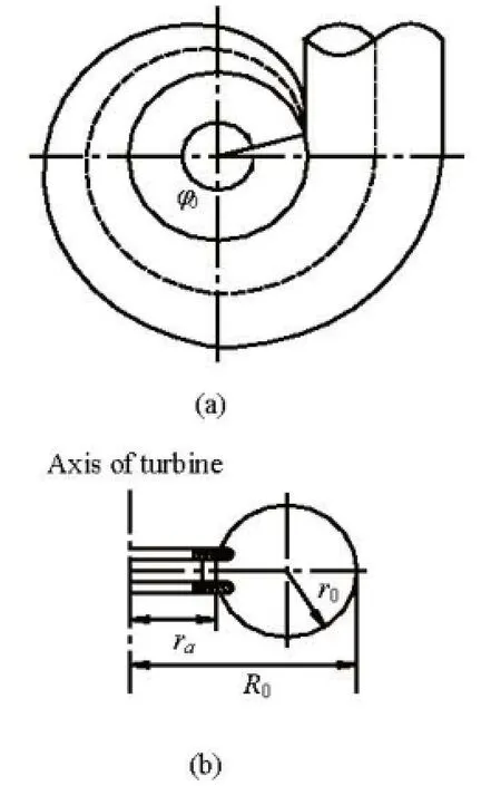
Fig.1 Perspective view of metal spiral casing and sectional view of spiral casing inlet

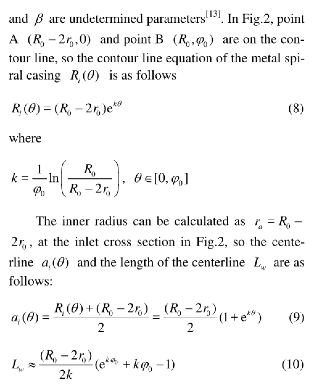
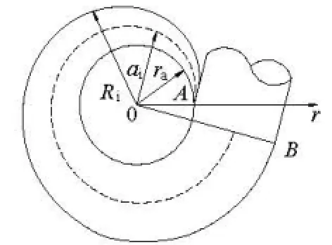
Fig.2 Polar coordinates in metal spiral casing
2. Equivalent pipe algorithm for metal spiral casing
The Bernoulli equation for the fluid unsteady flow between the cross section -jjand -i iis in the form
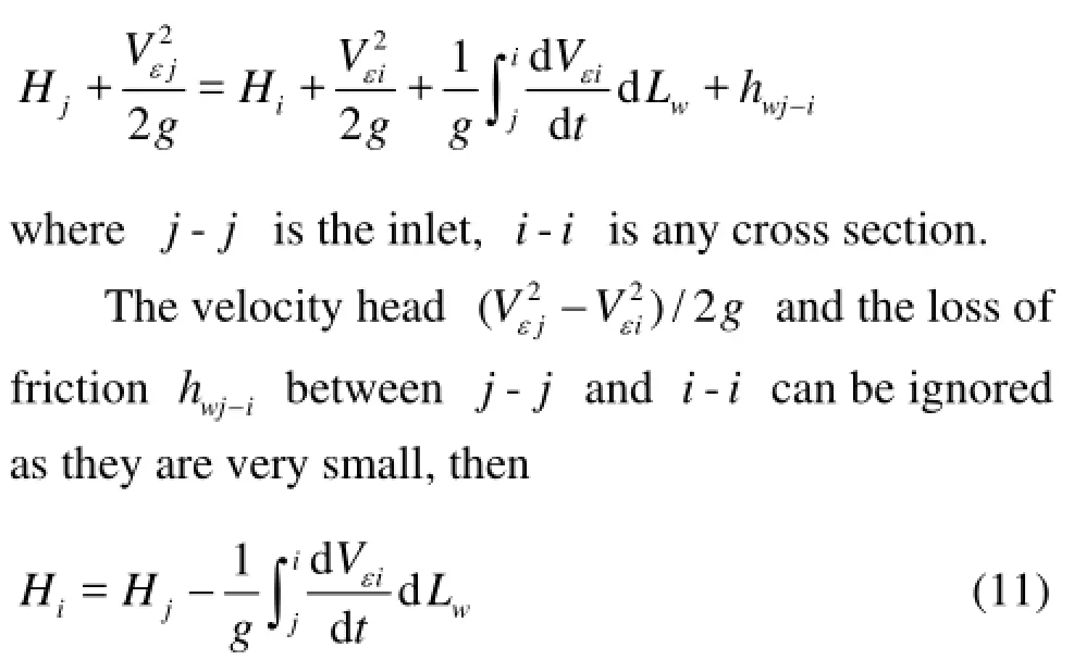


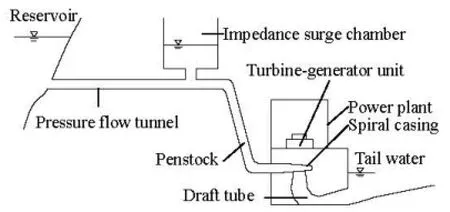
Fig.3 The diversion and power system of the large hydropower station investigated
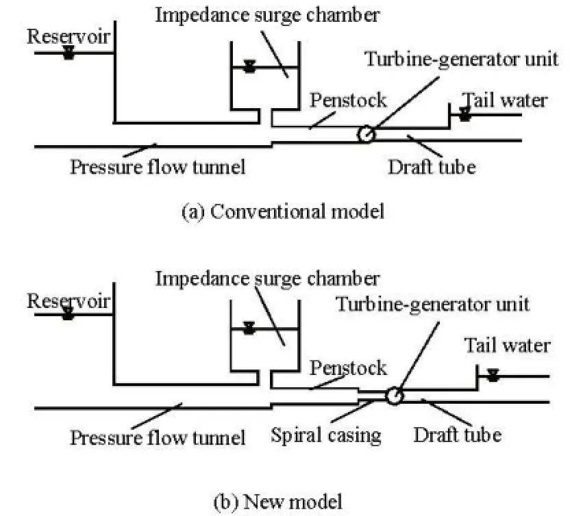
Fig.4 Conventional model and new model for hydraulic transient numerical computation
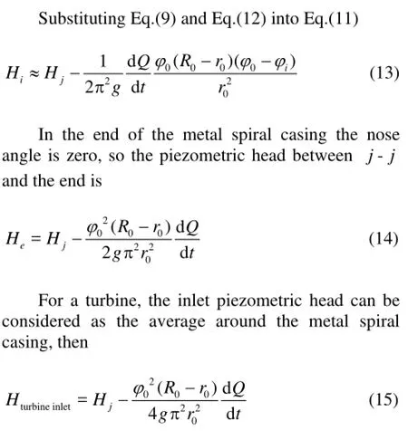


Table 1 Parameters of the computation models
When the water inertia is to be considered, in the computation, one may add an extended pipe of lengthLweand cross section areaAwebefore the turbine inlet. While the turbine output power is regulated, the turbine discharge capacity and the water hammer pressure in the penstock are inevitably affected by the water inertia.
3.Case studies
3.1Background of the prototype
The diversion and power system of a large hydropower station consists of the pressure flow tunnel, the impedance surge chamber, the penstock and three turbine-generator units. The length of the pressure flow tunnel is 16 293 m and the inner diameter is 8.6 m. The net diameter of the impedance surge chamber is 22 m, and the impedance orifice is 4.0 m in diameter. The total length of the penstock is 489.5 m, and the main penstock’s diameter is 7.0 m. The rated output of each turbine-generator unit is 140 MW, the rated head is 220.0 m and the rated speed is 300 r/min. The inlet radius of the metal spiral casing is 1.368 m and the nose angle is 6.021 rad. The distance between the outer shell of the metal spiral casing inlet and the turbine axis is 5.06 m, as shown in Fig.3.
In October 2011, the hydraulic transient prototype tests on the turbine-generator unit 1# were carried out by the group of the hydropower station proprietors and builders. The wicket gate opening curve and the turbine-generator speed curve were obtained by the turbine governor mechanism. The water hammer pressure in the metal spiral casing and the vacuum in the draft tube were measured, with the piezometers installed in the metal spiral casing and the draft tube.
3.2Governing equations
The governing equations include the continuity equation and the motion equation for the unsteady pressure flow in pipes. They can be written as[14]:
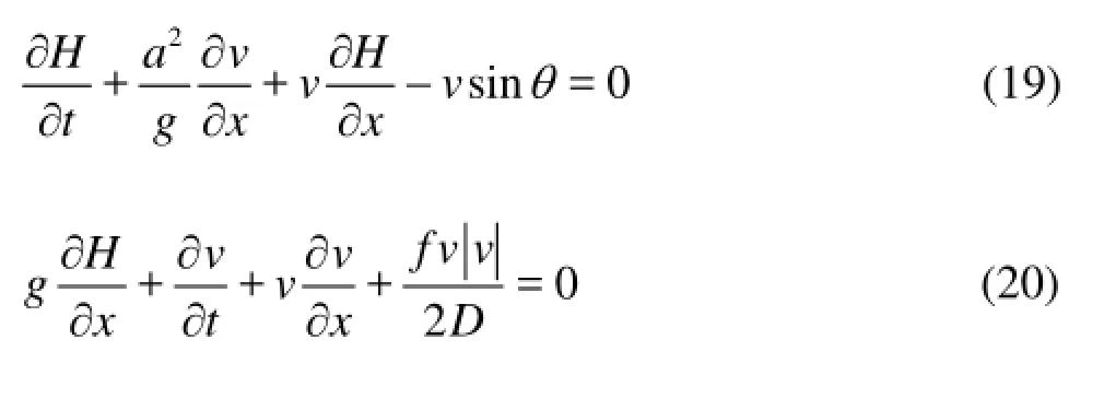
wherevis the flow velocity,His the piezometric head,ais the wave velocity of the water hammer,fis the friction coefficient,Dis the pipe diameter andθis the slope angle of the pipe centerline.
3.3Computation model
In order to verify the equivalent pipe algorithm and its hydraulic transient characteristics given in this study, two computation models are considered as follows:
Figures 4(a) and 4(b) are the conventional model and the new model in this paper for the hydraulic transient numerical computation, respectively, and with the additional factor,the equivalent pipe of the metal spiral casing,in the new model.
The parameters of the computation models are given in Table 1, where the length and the cross section area of the equivalent pipe are obtained from the Eq.(16) and Eq.(17).

Table 2 Hydraulic transient parameters of 1# unit
3.4Solution method and boundary conditions
The characteristics method[15,16]is used in this study. The reservoir level is taken as the inlet boundary, and the tail water level is taken as the outlet boundary. The impedance surge chamber boundary is also used, with a free water surface. The time step is set as 0.01 s. The hydraulic transient parameters are given in Table 2.

Fig.5 Wicket gate opening curve in working condition D1
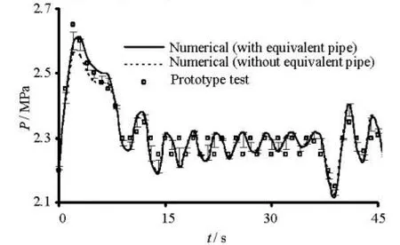
Fig.6 Water hammer pressure in spiral casing under working condition D1
3.5Results of the prototype tests and computations
The two models are computed by the characteristics method, where the water inertia is ignored conventionally in the former, and, is considered in the latter, with a factor, suggested in the paper. The results of the prototype tests, and those obtained by the conventional and new models under the working condition D1are shown in Fig.5-Fig.9, where the error bars are included, and the results under the working conditions D2and D3are very similar to those under the working condition D1, therefore, they are not shown.

Fig.7 Vacuum in draft tube under working condition D1
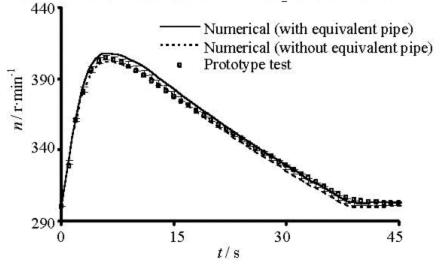
Fig.8 Turbine-generator unit speed under working condition D1
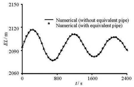
Fig.9 Water level in surge chamber under working condition D1
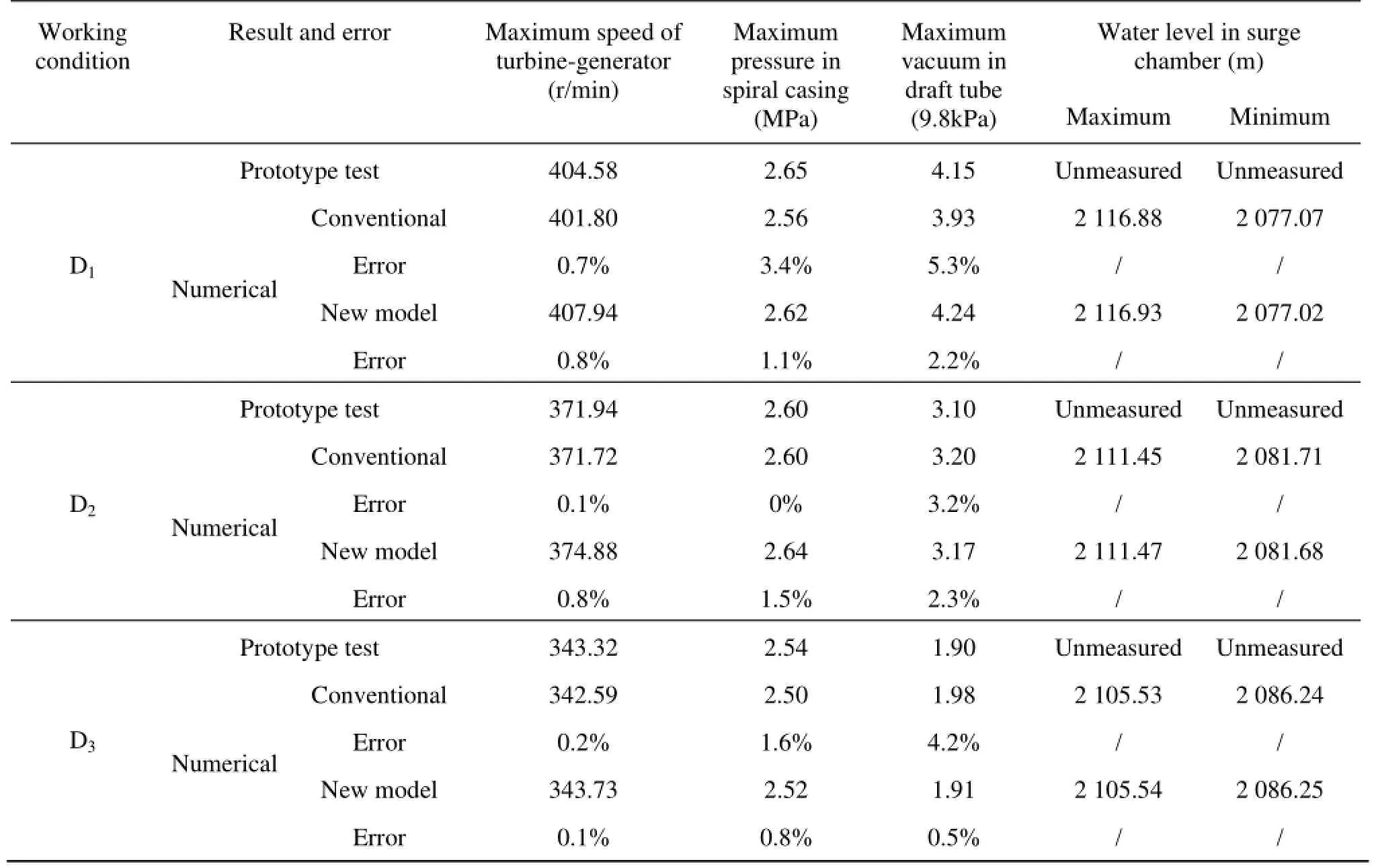
Table 3 Numerical computation and prototype tests under D1, D2and D3working conditions
4. Analyses and discussions
The wicket gate opening curve, the speed of the turbine-generator unit, the water hammer pressure in the spiral casing and the vacuum in the draft tube are the key factors in the hydraulic transient process. The accuracy of results would show whether the model is reasonable, credible and reliable or not. The comparison between numerical computation and prototype tests in working condition D1, D2and D3is given in Table 3.Analyses are as follows.
4.1Water hammer pressure characteristics
The water hammer pressure and the vacuum curves reach their peak values att=3 s. The conventional model’s errors (comparing to the prototype tests) for the maximum water hammer pressure are 3.4%, 0.0% and 1.6% under the working conditions D1, D2, D3, respectively,and the new model’s errors are 1.1%, 1.5%, and 0.8%; the conventional model’s errors for the maximum vacuum in the draft tube are 5.3%, 3.2% and 4.2%,and the new model’s errors are 2.2%, 2.3%, and 0.5%, which shows the new model’s improvement for the two factors.

4.2Turbine-generator speed characteristics
As shown in Fig.8, the results obtained by the two models show the same tendency and are in a good agreement with the prototype tests, where the peak of the turbine-generator unit speed is at =t5 s and the errors under the three working conditions of the two models are less than 1%.
In the start stage of the hydraulic transient process, the results obtained by the new model are still larger than those obtained by the conventional model, due to the pressure difference, because the speed of the turbine runner blades is increased in accordance with the pressure, so the turbine input power is increased. This phenomenon is reasonable.
4.3Surge chamber water level characteristics
The water levels in the surge chamber obtained by the two models are shown in Fig.9 and Table 3. The new model gives results in a good agreement with those obtained by the conventional model, with a difference less than 0.05 m, therefore, it can be concluded that the equivalent pipe of the metal spiral casing has almost no effect on the results of the water level in the surge chamber.
4.4Discussions
The spiral casing equation and the equivalent pipe algorithm are derived based on some basic assumptions. It is evident that one may ignore the flow viscosity and the loss of friction, but the assumptions (2) and (3) do have a little effect, and further improvement should be considered in these respects.
The length is expressed by an approximate formula and the error is less than 1% as compared with the computation tests.
For a water turbine, the inlet piezometric head can be considered as the average around the metal spiral casing, which can not be verified.
5. Conclusions
A new equation for the metal spiral casing is derived and an equivalent pipe algorithm is developed based on the equiangular spiral idea. It is shown that the equivalent pipe algorithm for the metal spiral casing based on the equiangular spiral idea is practical and reasonable with the equivalent pipe being considered as an extension of the penstock. The results of the prototype tests and the hydraulic transient computations by the new model (with the equivalent pipe) and the conventional model (without the equivalent pipe) are compared. It is shown that the equivalent pipe of the metal spiral casing has the following hydraulic transient characteristics:
(1) When the equivalent pipe of the metal spiral casing is taken as an extension of the penstock, the mathematical model for the diversion and power system would be improved in the hydraulic transient computation.
(2) The accuracy is increased and the error is evenly distributed with the use of the new model, with respect to the maximum speed of the turbine-generator unit, the maximum water hammer pressure in the spiral casing and the maximum vacuum in the draft tube, as compared with the conventional model.
(3) The equivalent pipe of the metal spiral casing has a certain impact on the speed of the turbine-generator unit, the pressure in the spiral casing and the vacuum in the draft tube in the hydraulic transient computation results, but it has almost no effect on the water level in the surge chamber.
[1] YANG Jian-dong, ZHAO Kun and LI Lin. Analysis on the causes of units 7 and 9 accidents at Sayano-Shushenskaya Hydropower Station[J]. Journal of Hydroelectric Engineering, 2011, (4): 226-234(in Chinese).
[2] CHENG Yong-guang, LI Jin-ping and YANG Jian-dong. Free surface-pressurized flow in ceiling-sloping tailrace tunnel of hydropower plant: Simulation by VOF model[J]. Journal of Hydraulic Research, 2007, 45(1): 88-99.
[3] GUO Jian-ping, ZHANG Li-xiang. Tripping transients in a complex pumping system with multi pumps in parallel[J]. Procedia Engineering, 2012, 31: 428-434.
[4] XU Wei-hui, GAO Chuan-chang and LIU Jun et al. Hydraulic transient numerical study of super-high parameter motor-pump in drainage system for mine emergency[J]. Energy Procedia, 2012, 14: 464-469.
[5] IZQUIERDO J., IGLESIAS P. L. Mathematical modelling of hydraulic transients in complex systems[J]. Mathematical and Computer Modelling, 2004, 39(4-5): 529-540.
[6] HUANG Hao, ZHANG Chang-bing and XING Zhi et al. Research on hydraulic transient process based on weakly compressible fluid[J].Water Resources and Power, 2012, 30(2): 81-85(in Chinese).
[7] ZHANG Li-xiang, ZHANG Hong-ming and WANG Zheng-jun et al. Analysis of state-changing water hammer in a long pipe[J].Journal of Hydrodynamics, Ser. B, 2004, 16(1): 52-60.
[8] XIA Lin-sheng, CHENG Yong-guang and ZHOU Daqing. 3-D simulation of transient flow patterns in a corridor-shaped air-cushion surge chamber based on computational fluid dynamics[J]. Journal of Hydrodynamics, 2013, 25(2): 249-257.
[9] LIANG Si-zhen, ZHANG Chang-bing and GE Jing. Research on object-oriented modeling of transient flow and application to the diversion system of hydropower station[J]. Journal of Hydraulic Engineering, 2010, 29(1): 147-151(in Chinese).
[10] BISWAS G., ESWARAN V. and GHAI G. et al. A numerical study on flow through the spiral casing of a hydraulic turbine[J]. International Journal for Numerical Methods in Fluids, 1998, 28(1): 143-156.
[11] YANG Kai-lin. The study of hydraulic transient in hydropower station and pumping plant[M]. Beijing, China: China Water Power Press, 2000, 122-131(in Chinese).
[12] ZHENG Yuan, JU Xiao-ming and CHENG Yun-shan. Water turbine[M]. Beijing, China: China Water Power Press, 2007, 97(in Chinese).
[13] LOCKWOOD E. H. A book of curves[M]. London, UK: Cambridge University Press, 1961, 108.
[14] LIN Jin-song, JU Jiang and ZHU Liang et al. Application of numerical simulation of water transient process in hydropower station[J]. Journal of Hydraulic Engineering, 2010, 29(1): 31-37(in Chinese).
[15] CHEN Jiang-lin, LV Hong-xing and SHI Xi et al. Analysis of water hammer process of tee pipe considering local head loss by using characteristic line method[J]. Water Saving Irrigation, 2011, (10): 17-20(in Chinese).
[16] WANG Chao, YANG Jian-dong. Solution for shortpipe problem in calculation of unsteady flow with characteristics method[J]. Water Resources and Power, 2013, 31(7): 77-80(in Chinese).
10.1016/S1001-6058(14)60016-0
* Project supported by the National Natural Science Foundation of China (Grant No. 51179114).
Biography: PENG Xiao-dong (1984-), Male, Ph. D. Candidate
LIU Shan-jun,
E-mail: drliushanjun@vip.sina.com
- 水动力学研究与进展 B辑的其它文章
- An ocean circulation model based on Eulerian forward-backward difference scheme and three-dimensional, primitive equations and its application in regional simulations*
- Detrended analysis of Reynolds stress in a decaying turbulent flow in a wind tunnel with active grids*
- Estimation of discharge and its distribution in compound channels*
- Influences of soil hydraulic and mechanical parameters on land subsidence and ground fissures caused by groundwater exploitation*
- A hybrid DEM/CFD approach for solid-liquid flows*
- Simulation of buoyancy-induced turbulent flow from a hot horizontal jet*

