Decomposition of the Unsteady Wave Patterns for Bessho form Translating-Pulsating Source Green Function
XIAO Wenbin, and DONG Wencai
Department of Naval Architecture, Naval University of Engineering, Wuhan 430033, P. R. China
Decomposition of the Unsteady Wave Patterns for Bessho form Translating-Pulsating Source Green Function
XIAO Wenbin, and DONG Wencai*
Department of Naval Architecture, Naval University of Engineering, Wuhan 430033, P. R. China
In order to interpret the physical feature of Bessho form translating-pulsating source Green function, the phase function is extracted from the integral representation and stationary-phase analysis is carried out in this paper. The complex characteristics of the integral variable and segmentation of the integral intervals are discussed in m complex plane. In θ space, the interval [-π/2+φ, -π/2+φ-iε] is dominant in the near-field flow, and there is a one-to-one correspondence between the real intervals in m space and the unsteady wave patterns in far field. If 4τ>1 (τ is the Brard number), there are three kinds of propagation wave patterns such as ring-fan wave pattern, fan wave pattern and inner V wave pattern, and if 0<4τ<1, a ring wave pattern, an outer V and inner V wave pattern are presented in far field. The ring-fan or ring wave pattern corresponds to the interval [-π+α, -π/2+φ] for integral terms about k2, and the fan or outer V wave pattern and inner V wave pattern correspond to [-π+α, -π/2) and (-π/2, -π/2+φ] respectively for terms about k1. Numerical result shows that it is beneficial to decompose the unsteady wave patterns under the condition of τ≠0 by converting the integral variable θ to m. In addition, the constant-phase curve equations are derived when the source is performing only pulsating or translating.
translating-pulsating source; unsteady wave patterns; stationary-phase analysis; near-field flow component; wave component
1 Introduction
Three dimensional (3D) translating-pulsating source Green function is a key kernel for seakeeping calculation and analysis, whose advantage is an automatic satisfaction of the linearized free-surface and radiation conditions. There are now several forms in polar Fourier representation of 3D translating-pulsating source Green function in frequency domain, such as the Havelock form (Havelock, 1958), Michell form (Hanaoka, 1953) and Bessho form (Bessho, 1977). Green function of the Bessho form is considered as the best type in numerical computation (Matao, 1992) with a single integral form and all its mathematical terms are elementary functions. Some rapid and stable integral calculations have been carried out by Iwashita and Ohkusu (1989), Du and Wu (1998) and Maury et al. (2003), and some results (Bruzzone et al., 2001; Du et al., 2005, 2012) had been applied to investigate the free motions and excited wave forces of a ship advancing in waves.
In the study about the wave patterns of 3D translating-pulsating source, Noblesse and Hendrix (1992) obtained the far-field waves of translating-pulsating source in Cartesian coordinate system, and explored the relationship between the wave characteristics, forward speed and oscillating parameters. Further, Noblesse and Chen (1995) decomposed the free-surface potential into a single integral and a double Fourier integral, corresponding to the wave component and local component respectively. By an asymptotic analysis, Chen and Diebold (1999) then obtained the analytical expressions of the transverse and divergent waves in the far field. More theoretical studies about the wave patterns are presented in Chen (2002) and Noblesse and Yang (2003), in which wave descriptions including the surface tension effect and a simpler far-field representation are summarized. Experiments using a modified Wigley model were carried out to obtain the unsteady waves and a highly accurate method was applied to measure the diffraction waves by Iwashita et al. (2011). In terms of wave pattern application, Ohkusu (1980) and Kashiwagi (2010) evaluated the added resistance by means of unsteady wave pattern analysis, which is beneficial for the deeper hydrodynamic understanding of ship-generated waves.
Inspired by the ideas of Noblesse and Hendrix (1992), Xu (2012) studied the far-field wave patterns of Havelock form translating-pulsating source by using a special variable substitution and found that parallel waves would appear at integral end, which could yet be cancelled out between different terms. For Michell form, Miao et al. (1995) derived the constant-phase curve equations aboutthe integral variable, and probed into the far-field radiation behaviors and its propagation properties. Bessho form Green function may achieve some numerical advantages in seakeeping calculations, but some researchers (Matao, 1992; Xu and Dong, 2011) hold the view that its physical feature is not so clear as the Havelock form or Michell form, which is largely due to the complexity of the integral path in complex plane.
This paper mainly investigates the unsteady wave patterns for Bessho form Green function by performing stationary-phase analysis method. The constant-phase curve equations are achieved from the integral representation and its transformation. The paper focuses on the explicit determination of near-field flow and wave components for Bessho form translating-pulsating source, and the relationships between the wave behavior and the integral interval in complex plane. If the physical feature of Bessho form is more definite, it is expected to further guide its practical application in seakeeping problem.
2 Integral Representation of Bessho Form Green Function
A right-handed equilibrium axis system oxyz is defined in the condition of deep water with the origin o on the plane of undisturbed free surface, and the z-axis is positive upwards. The axis system translates with a uniform forward speed U in the positive x direction. The 3D Green function at field point (x, y, z) is defined as a speed dependent velocity potential G of a translating-pulsating source at (ξ, η, ζ) with an oscillating frequency ω, which is given by Bessho (1977) as
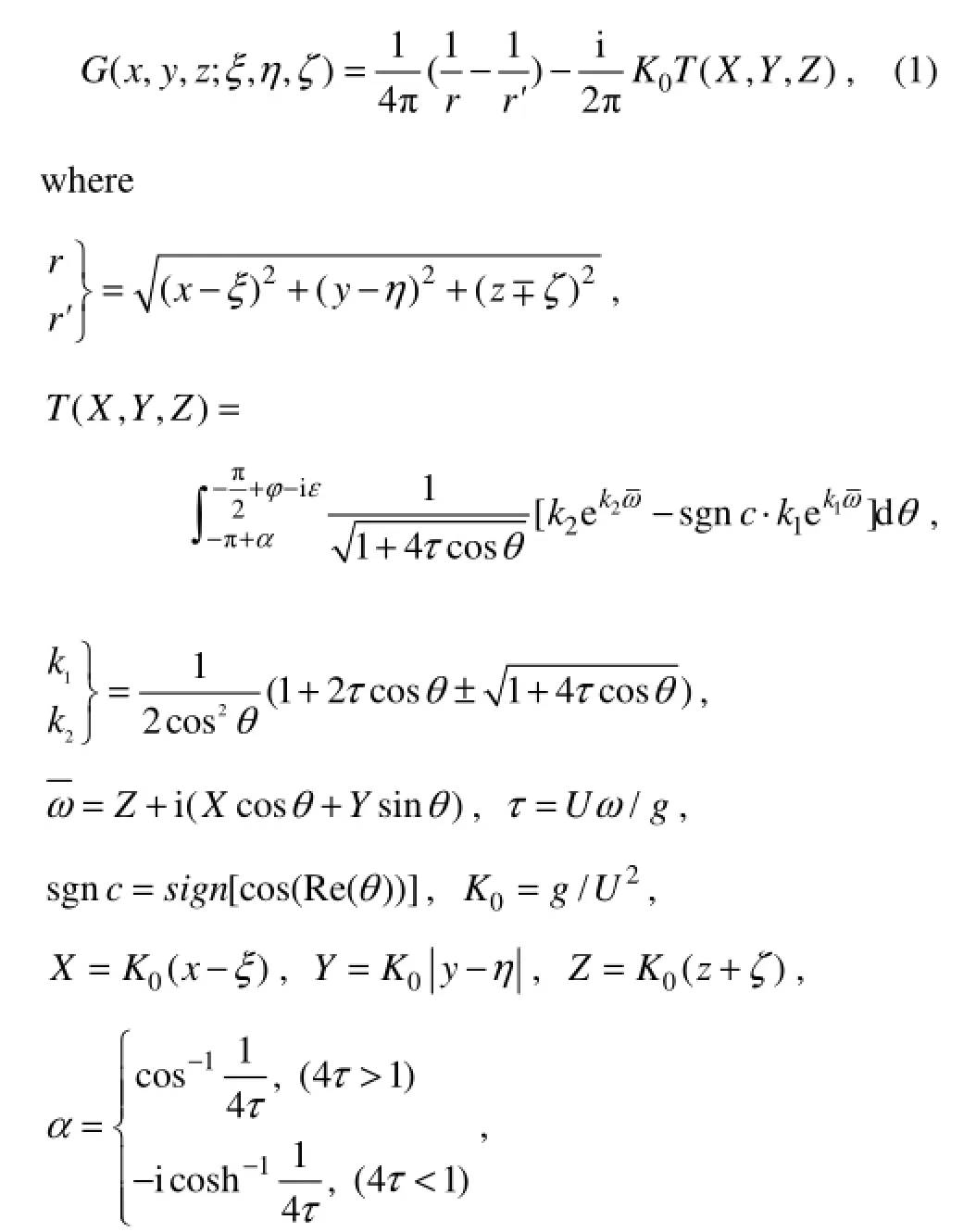

k1,2is the generalized wave number and sign is the symbolic function. It is obvious that the integral path of Eq. (1) is located in θ space, which can be divided into two kinds of conditions according to the value of τ, as depicted in Fig.1.
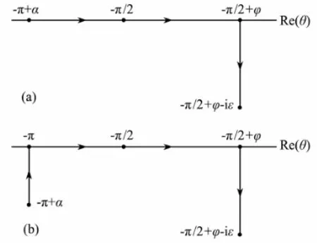
Fig.1 Integral path of Eq. (1) in θ space. (a) 4τ>1 and (b) 4τ<1.
A new integration variable of M=sgnc·m=sgnc·k1cosθ is introduced and a closed curve in M space (or m space) is built for k1. By the Cauchy integral theorem, the terms about k1can be rewritten (Iwashita and Ohkusu, 1989) as
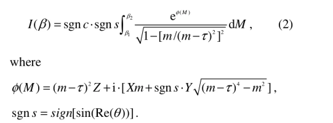
The lower limit β1and upper limit β2in Eq. (2) are determined by the actual division of integral interval. The terms about k2also can be replaced by a new variable, with a similar result to that with Eq. (2).
3 Decomposition of Near-Field Flow and Wave Components in Bessho Form
In Eq. (2), ()Mφ represents some characteristics of the exponential part of integrating function, whose real part is the oscillating amplitude and imaginary part is the phase value. So the phase function of Bessho form can be defined by the imaginary part of ()Mφ as

According to the traits of phase function, the wave pattern in far field can be determined by stationary-phase analysis method. If dψ/dM = 0 in Eq. (3), it is easy to obtain


By substituting the Eq. (4b) in Eq. (3), the parametric equation of stationary-phase curve can be performed as Eq. (5)
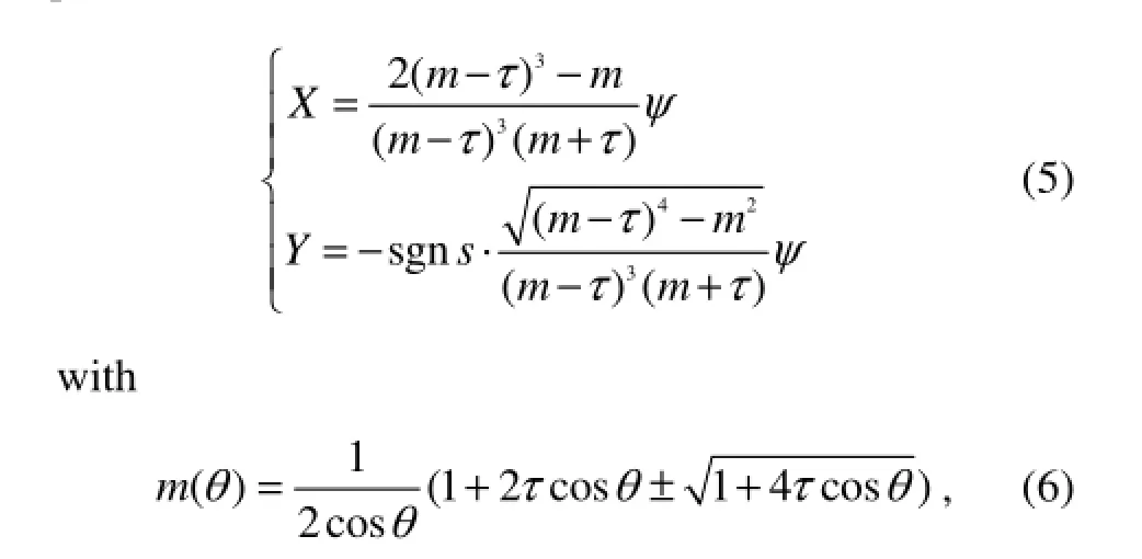
and the range of variable θ depends on actual integral path in Fig.1. According to Eq. (5), the position of the source point and field point is related to the unsteady wave pattern at specific instants, such as those for the occurrence of wave crests and wave hollows. In m space, the integral path is converted, which is shown in Figs.2 and 3.
Limits of integration about m(0), m(-π+α) and m(-π/2) can be defined as Eqs. (7a), (7b), and (7c).
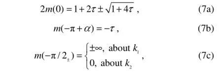
It can be seen from Eq. (3) that there is no point of stationary phase in the intervals identified by the dashed lines in Figs.2 and 3, where the imaginary part of m is not zero, because X and Y must be real numbers. Therefore, the corresponding terms in Eq. (1) have no disturbance in far field, which can be defined as the near-field flow component. The variable m is real in the intervals presented by the solid lines in Figs.2 and 3, where the stationary phase of ψ(M) is in existence, so the contribution of the corresponding terms in Eq. (1) is dominant in far field. The solid-lines intervals, defining the wave component, can be divided into three parts such as D1, D2and AA, constituting the far-field waves of Green function. Particularly, the terms about k1have strong oscillations in the vicinity of ±π/2 of θ space, which deserves more attention while calculating the integration. However, the terms about k2are out of singularity along its whole interval. In Table 1, the detailed integral interval for the near-field flow and wave components are presented in the complex plane.
When 4τ<1, the integral path in θ space consists of two complex intervals and one real interval. It is very interesting that the complex interval [-π+α, -π] is converted to real in m space, and the special value m(-π) is located on different sides of -τ for k1and k2respectively. This interval merging phenomenon is beneficial not only to the integration calculation, but also to the decomposition of unsteady wave patterns.
The stationary-phase analysis above is illuminated in m space, whereas the original integration variable is in the θ space for Bessho form Green function. In order to make sure that the Green function will keep its characters by performing the variable substitution, m (or M) and θ must keep the monotonic relationship in different intervals, which is significant for the wave pattern analysis.
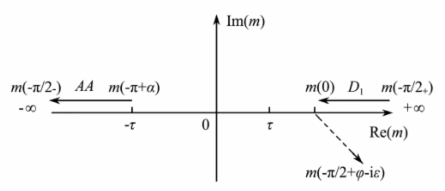
Fig.2 The new integral path for terms about k1in m space.
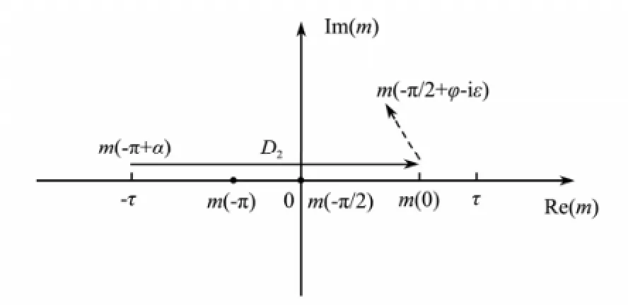
Fig.3 The new integral path for terms about k2in m space.

Table 1 Integral interval in complex plane for the near-field flow and wave components
4 Unsteady Wave Patterns of Bessho Form Green Function
An advancing ship in deep water will generate unsteady waves and these wave patterns depend on both the encounter frequency and forward speed. For frequency domain method of Green function, the unsteady wave of a harmonically oscillating source at forward speed can be expressed by the constant-phase curve equation introduced from phase function.
In order to find the wave systems together with theircharacteristics, the parametric Eq. (5) can be numerically calculated by different intervals in far field. Three stationary curves can be obtained from Eq. (5), and the other three curves are determined by symmetric transformation for Y is symmetric of the x axis. Fig.4 depicts the wave patterns propagating outward when the source is located at (ξ ,η, ζ)=(0,0,-0.1). This figure shows that, for the value of 4τ>1, there are three distinct wave patterns such as inner V waves from D1, fan waves from D2and ringfan waves from AA. For the value of 4τ<1, D1and D2correspond to the inner V waves and outer V waves respectively, and the ring waves are from AA, whose forward wavelengths are shorter than those at the backward positions of the source. The results of these propagation wave patterns are consistent with those obtained by Noblesse and Hendrix (1992).
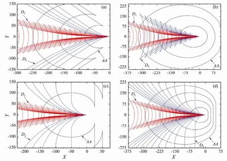
Fig.4 Constant-phase curves of far wave patterns when the source is located at (0,0,0.1)-. (a) τ=0.35, (b) τ=0.2, (c) τ=0.25+, and (d) τ=0.25-.
Fig.4 shows that the wave patterns from D2and AA are closely connected to parameter τ. With an increasing forward speed U and oscillating frequency ω, two waves above tend to propagate downstream of the source, in which the ring waves are degenerated into ring-fan waves and outer V waves into fan waves. On the other hand, the wave patterns from D1include the transverse and divergent waves all the time. It is important to note that when excited waves would appear upstream of the ship, Chen and Diebold (1999) pointed out that the ring-fan waves would not propagate forward if τ >2/27, which means that the excited waves would not be observed in front of an advancing ship. Fig.5 illustrates the cusp angles δ (to the negative ox direction) of ring-fan waves at different values τ. Numerical calculation demonstrates that cusp angle δ is between 0˚ and 125.26˚, which agrees well with Noblesse and Hendrix (1992) and Xu (2012).
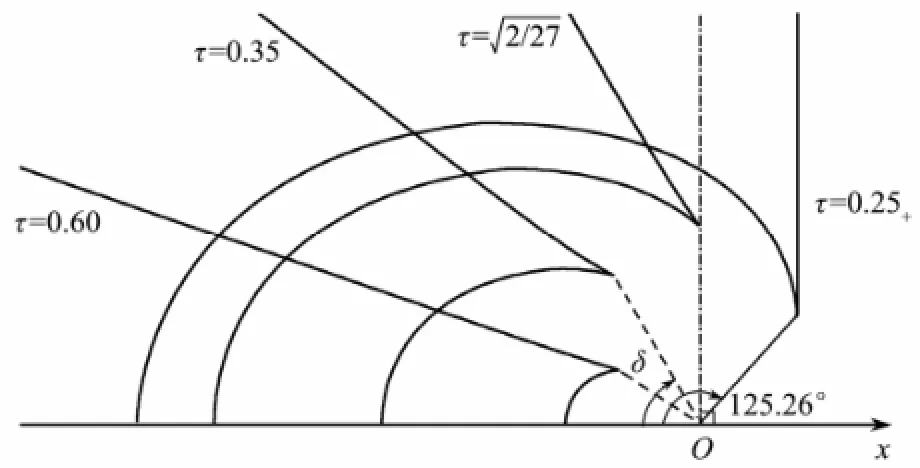
Fig.5 Cusp angle δ of ring-fan waves at different value of τ.
5 Constant-Phase Curves and Wave Patterns in the Condition of τ=0
The previous section mainly discusses the wave patterns in the case of τ≠0. The special wave patterns of the Bessho form Green function need further study when τ=0. In physical phenomenon, there are only ring waves if the source is stationary. When the oscillating frequency of a source is equal to zero, the source will move forward at a certain speed with no oscillating motions, and the wave pattern here is known as Kelvin wave pattern (Miao et al., 1995; Xu, 2012).
By performing κ1,2=K0k1,2in Eq. (1), κ then possesses the same physics dimension as wave number, and the integrand can be rewritten as Eq. (8).

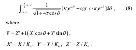
Three parameters X', Y' and Z' now directly demote the relative distance between the source point and field point. By stationary-phase analysis method, the phase function extracted from Eq. (8) is now written as

When the frequency ω≠0 and forward speed U→0, parameter κ1tends to +∞, and the limit of terms about κ1is shown in Eq. (10).

Therefore, the wave patterns in far field don’t exist for κ1. If the forward speed U=0 and κ2=ω2/g, the constant-phase curve equation can be written as Eq. (11).
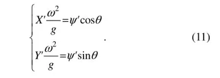


Fig.6 and Fig.7 illustrate the wave shape under the condition of τ=0. In Fig.6, the source’s oscillating frequency ω≠0, whose constant-phase curves are all circles with the same center o and same wavelengths in all directions. In Fig.7, the source’s forward speed U≠0 and the constant-phase curves are steady Kelvin wave patterns. The wave patterns of the two presented cases agree well with the results obtained by Faltinsen (2005) and Xu (2012), which proves that the wave patterns of Bessho form Green function are still describable when τ=0.
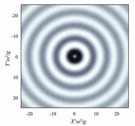
Fig.6 Wave shape with ω≠0 and U=0.
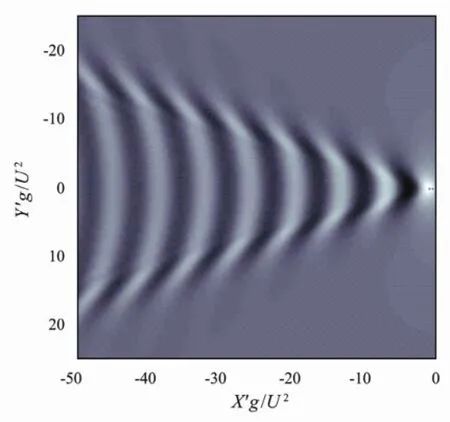
Fig.7 Wave shape with U≠0 and ω=0.
6 Conclusions
1) The constant-phase curves can be obtained through stationary-phase analysis for the Bessho form translating-pulsating source. The different intervals are determined according to the features of constant-phase curves for the near-field flow and wave components. And the two field components are related to integral intervals in θ space and it is a fast way to determine them by converting the integral variable θ to m.
2) In θ space, the near-field flow component is confined to the interval[-π/2+φ,-π/2+φ-iε], and there is a one-to-one correspondence between the real intervals in m space and unsteady waves in far field, in which the ring-fan waves or ring waves correspond to the interval [-π+α,-π/2+φ] for terms about k2, the fan waves or outer V waves correspond to the interval [-π+α,-π/2) for terms about k1, and the inner V waves to the interval(-π/2,-π/2+φ]for terms about k1.
3) The mathematical expressions of propagating wave patterns can be derived not only under the condition of τ≠0 but also τ=0 from the integral representation and the transformation of Bessho form Green function.
4) Most importantly, the physical feature of Bessho form Green function is clarified by the research of the present paper. The application of this numerically advantageous type of Green function form to ocean structure’s seakeeping calculation can also be expanded with a clear and definite physical feature.
Acknowledgements
This study has received financial support from the National Natural Science Foundation of China under Grant No. 50879090 and the Key Program of Hydrodynamics of China under Grant No.9140A14030712JB11044.
Bessho, M., 1977. On the fundamental singularity in the theory of ship motion in a seaway. Memoirs of the Defense Academy of Japan, 17 (8): 95-105.
Bruzzone, D., Gualeni, P., and Sebastiani, L., 2001. Effects of different three dimensional formulations on the seakeeping computations of high speed hulls. 8th International Symposium on Practical Design of Ships and Other Floating Structures. Shanghai, Vol. 1, 547-553.
Chen, X. B., 2002. Role of surface tension in modeling ship waves. 17th International Workshop on Water Waves and Floating Bodies. Cambridge, UK, 1-4.
Chen, X. B., and Diebold, L., 1999. Analytical expressions of unsteady ship wave patterns. 14th International Workshop on Water Waves and Floating Bodies. Port Huron, USA, 25-28.
Du, S. X., and Wu, Y. S., 1998. A fast evaluation method for Bessho form translating-pulsating source Green’s function. Shipbuilding of China, 2: 40-48 (in Chinese with English abstract).
Du, S. X., Hudson, D. A., Price, W. G., and Temarel, P., 2005. Prediction of three-dimensional seakeeping characteristics of fast hull forms: Influence of the line integral terms. International Conference on Fast Sea Transportation. St. Petersburg, Russia, 1-8.
Du, S. X., Hudson, D. A., Price, W. G., and Temarel, P., 2012. An investigation into the hydrodynamic analysis of vessels with a zero or forward speed. Proceedings of the Institution of Mechanical Engineers, Part M: Journal of Engineering for the Maritime Environment, 226 (2): 83-102.
Faltinsen, O. M., 2005. Hydrodynamics of High-Speed Marine Vehicles. Cambridge University Press, UK, 454pp.
Hanaoka, T., 1953. On the velocity potential in Michell’s system and the configuration of the wave-Ridges due to a moving ship. Journal of the Society of Naval Architects of Japan, 93: 1-10.
Havelock, T. H., 1958. The effect of speed of advance upon the damping of the heave and pitch. Transactions Institution Naval Architects, 100: 131-135.
Iwashita, H., and Ohkusu, M., 1989. Hydrodynamic forces on a ship moving with forward speed in waves. Journal of the Society of Naval Architects of Japan, 166: 87-109.
Iwashita, H., Elangovan, M., Kashiwagi, M., and Sasakawa, T., 2011. On an unsteady wave pattern analysis of ships advancing in waves. Journal of the Japan Society of Naval Architects and Ocean Engineers, 13: 95-106 (in Japanese with English abstract).
Kashiwagi, M., 2010. Prediction of added resistance by means of unsteady wave-pattern analysis. 25th International Workshop on Water Waves and Floating Bodies. Harbin, China, 1-4.
Matao, T., 1992. 3D Green function of oscillating body with forward speed on water of finite depth. Journal of Kansai Society of Naval Architects of Japan, 217: 67-75.
Maury, C., Delhommeau, G., Ba, M., Boin, J. P., and Guibaud, M., 2003. Comparison between numerical computations and experiments for seakeeping on ship models with forward speed. Journal of Ship Research, 47 (4): 347-364.
Miao, G. P., Liu, Y. Z., Yang, Q. Z., and Liu, Z. Y., 1995. On the 3-D pulsating source of Michell’s type with forward speed. Shipbuilding of China, 4: 1-11 (in Chinese with English abstract).
Noblesse, F., and Chen, X. B., 1995. Decomposition of freesurface effects into wave and near-field components. Ship Technology Research, 42 (4): 167-185.
Noblesse, F., and Hendrix, D., 1992. On the theory of potential flow about a ship advancing in waves. Journal of Ship Research, 36 (1): 17-29.
Noblesse, F., and Yang, C., 2003. Farfield waves. 18th International Workshop on Water Waves and Floating Bodies. Le Croisic, France, 1-5.
Ohkusu, M., 1980. Added resistance in waves in the light of unsteady wave pattern analysis. Proceedings of 13th Symposium on Naval Hydrodynamics. Tokyo, Japan, 413-425.
Xu, Y., 2012. Study on the mechanism of hydrodynamic interaction between multiple ships advancing in waves at close proximity. PhD thesis, Naval University of Engineering, Wuhan, 178pp (in Chinese with English abstract).
Xu, Y., and Dong, W. C., 2011. Study on characteristics of 3-D translating-pulsating source Green function of deep-water Havelock form and its fast integration method. China Ocean Engineering, 25 (3): 365-380.
(Edited by Xie Jun)
(Received January 15, 2013; revised May 28, 2013; accepted May 21, 2014)
© Ocean University of China, Science Press and Springer-Verlag Berlin Heidelberg 2014
* Corresponding author. E-mail: haigongdwc@163.com
 Journal of Ocean University of China2014年5期
- Journal of Ocean University of China的其它文章
- Sedimentary Evolution of the Holocene Subaqueous Clinoform off the Southern Shandong Peninsula in the Western South Yellow Sea
- Identification of Fucans from Four Species of Sea Cucumber by High Temperature1H NMR
- Experimental Study on the Flow Around Two Tandem Cylinders with Unequal Diameters
- Revision of P-wave Velocity and Thickness of Hydrate Layer in Shenhu Area, South China Sea
- Study on Internal Waves Generated by Tidal Flow over Critical Topography
- Isolation and Characterization of Fucoidans from Five Brown Algae and Evaluation of Their Antioxidant Activity
