Hybrid Elements for Modelling Squeeze Film Effects Coupled with Structural Interactions in Vibratory MEMS Devices
A.RoychowdhuryA.NandyC.S.Jog and R.Pratap
1 Introduction
The numerous applications of vibratory MEMS devices such as resonators,accelerometers,gyroscopes,etc.,in everyday gadgets such as smart phones,tablet computers and other ‘smart’consumer goods have led to an increasing interest in making such devices more energy efficient.Thus the understanding of various dissipation mechanisms in these devices is of immense importance to MEMS designers.Typically,such MEMS devices have a plate like structure with lateral dimensions much larger than the plate thickness as well as the gap between the fixed substrate and the structure.For vibrations normal to the fixed substrate,the trapped air(see Fig.1)acts like a squeeze film and offers both stiffness and damping to the vibrating structure.This phenomenon is called squeeze film effect.Under such operating conditions,for devices fabricated with high Q(mechanical Quality factor)materials such as silicon(which have low material loss or internal damping),squeeze film damping is usually the dominant energy dissipation mechanism[Bao and Yang(2007)].The squeeze film effects result in a change in the dynamic characteristics of vibratory MEMS devices[Pratap,Mohite,and Pandey(2007);Pratap and Roychowdhury(2014)].Therefore,MEMS designers need to take the squeeze film induced stiffness and damping into consideration in the design of such devices.Most often vibratory MEMS devices use electrostatics for actuation and sensing.Therefore for accurate modelling of squeeze film effects one needs to solve the coupled problem of electrostatics,structural elasticity and fluid mechanics.

Figure 1:A schematic representation of squeeze flow between an oscillating plate and a fixed substrate
The thin fluid domain is traditionally modelled using the Reynolds equation[Blech(1983)]as developed in lubrication theory.Assuming rigid plate motion one can decouple the Reynolds equation from the structural vibration equation and linearize it under suitable conditions to obtain analytical expressions for squeeze film stiffness and damping.[Darling,Hivick,and Xu(1997)]used a Greens function approach to solve the Reynolds equation assuming trivial pressure boundary conditions and rigid plate motion,and presented analytical expressions for squeeze film pressure and forces.However,for truly modelling the fluid structure interaction problem of squeeze film,one has to account for the spatially variable air gap created due to the flexure of the elastic vibrating structure and the elasticity equation has to be coupled with the fluid equation.[McCarthy,Adams,McGruer,and Potter(2002)]used a transient finite difference method to study cantilever micro-switches with pressure distribution taken to be invariant along the width and parabolic along the length.The results showed good agreement with experimental measurements.Pandey and Pratap(2007)used Greens functions for solving the compressible linearized Reynolds equation and used the modal projection technique in ANSYS for the coupled fluid structure problem in order to solve for squeeze film stiffness and damping for several flexural modes of a cantilever beam.The analytical and numerical results were found to be in good agreement with experimental results.Li,Hu,and Fang(2007)also attempted to solve the coupled Euler Bernoulli beam equation and Reynolds equation for squeeze film by modelling the pressure as a parabolic function along the beam width and a cosine series along the beam length.They used this approach to model a fixed-fixed beam and a cantilever with static bias deflection.Hannot and Rixen(2009)presented yet another approach to solve the coupled fluid-structure problem.The mechanical equations were modelled using a non-linear Newmark time integration scheme and the trapezoidal rule was used for the fluid equations.
The approaches of various groups discussed above attempt to model the coupled fluid-elasticity equation.However these approaches involve either approximation to the pressure distribution or iterative solution schemes which are cumbersome and not truly coupled.In our prior work[Roychowdhury,Nandy,Jog,and Pratap(2013)],we presented a single step solution methodology to solve the fluid-structure problem of squeeze film in a truly coupled form.We used 27 node displacement based 3D elements and our numerical results showed good agreement with published experimental data from literature.However it is to be noted that displacement based elements suffer from an inherent drawback of locking in modelling geometries that have large lateral dimensions compared to the thickness.
The Hybrid finite elements[Atluri(1975);Pian and Sumihara(1984);Pian and Tong(1986)],which are based on two field variational formulation with displacement and stresses interpolated independently,are seen to be much less susceptible to locking.The hybrid elements show greater accuracy at much lower mesh sizes than displacement based elements and can model both chunky geometries as well as plate like structures[Jog(2005);Jog(2010)].
2Dand 3Dcurvilinearhybrid stresselementshave been developed in[Atluri(1984);Punch and Atluri(1984);Rubinstein,Punch,and Atluri(1983)],where symmetry group theory has been used to select proper stress modes such that the LBB(Lady˘zenskaja–Bab˘uska–Brezzi)condition[Brezzi(1974)]is satisfied.This ensures rank sufficiency of the element stiffness matrix.A distortion sensitivity study has been done in[Punch and Atluri(1984)].In the context of hybrid stress FEM there are problems of kinematic modes and frame dependence which are taken care of by applying symmetry group theory.In[Rubinstein,Punch,and Atluri(1983)]stress shape functions are scaled in a locally embedded co-ordinate system.
Recentadvancements in the field ofhybrid elementsinvolve procedureswhere multifield variational principles are not used and hence the LBB conditions need not be satisfied for the elements developed.
In the work by[Atluri,Han,and Rajendran(2004)],where they proposed a mixed approach to the implementation of meshless finite volume method,strains were independently assumed and collocated to assumed displacements at nodal points.The absence of derivatives resulted in the method being more computationally efficient.Several recent studies progressed on similar lines with different collocation approaches.Dong and Atluri(2011)also assume an independently varying strain field which is related to the strain derived from independently assumed displacements at finite number of collocation points.It has been shown that in order for the elements to pass the patch test,the collocation points are chosen from Gauss quadrature points.Different elements are developed by varying the choice of the assumed strain field and the collocation points.An invariant,locking free,insensitive to mesh distortion element is found after several numerical experiments.
The work by[Dong and Atluri(2011)]has been extended by[Bishay and Atluri(2012)],where higher order 2D as well as lower and higher order 3D mixed finite elements have been developed following the methodology mentioned in[Dong and Atluri(2011)].The performance and efficiency of these new mixed lockless finite elements are shown to be much better than that of the conventional displacement based elements and even the two field variation elements developed by[Pian and Sumihara(1984)].
In another recent study[Dong,Ei-Gizawy,Juhany,and Atluri(2014a)],a four node 2D element is developed for modelling functionally graded materials or laminated composite beams.The work by[Dong and Atluri(2011)]is improved upon and a five parameter linearly varying cartesian strain field is selected.The assumed strain field is related to the strains derived from the displacement field by enforcing five pre-de fined constraints at five pre-selected collocation points.The rationale behind choosing the five constraints(four axial stretch and one change in angle between two fibres)was to capture the basic kinematics of the 4 node element.The element so developed was shown to be superior to existing hybrid lower order elements and primal elements in modelling homogeneous beams specially if distortion in elements is considered.Whereas the elements developed by[Pian and Sumihara(1984)]showed huge errors in modelling functionally graded materials,the element discussed in[Dong,Ei-Gizawy,Juhany,and Atluri(2014a)]showed very accurate results.
The work by[Dong,Ei-Gizawy,Juhany,and Atluri(2014a)]was extended to develop 3D lower order lockless mixed collocation elements in the work by[Dong,Ei-Gizawy,Juhany,and Atluri(2014b)].Again a linearly assumed strain field was chosen and its compatibility with derived strain from displacements was enforced using 18 pre-defined constraints at 18 pre-selected collocation points.The 3D element so developed was shown to be very accurate in solving for in plane stresses for functionally graded materials and laminated composite beams.Also z-pin reinforced laminated structures can be modelled by simply adding the stiffness of the z-pins to the stiffness matrix of the element developed.
The choice of stress shape function in the present work follows from[Jog(2010)]where more terms than the minimum number of terms required to satisfy LBB condition[Xue,Karlovitz,and Atluri(1985)]have been chosen.It has been shown in[Jog(2010)]through a series of examples in linear and non-linear elasticity that the present hybrid element can take care both shear and membrane locking(it happens when there is curvature).For membrane locking,the 27 node hybrid element showed far better results than its displacement based counterpart(see Figure 2 and Table 1 in[Jog(2010)])
As squeeze film geometries in MEMS structures typically consists of plate like geometries with large lateral dimensions compared to the thickness,the hybrid element would be a better choice compared to displacement based elements for modelling squeeze film effects.In modelling high frequency problems,the effectiveness of hybrid elements is more pronounced.In this work we develop a coupled hybrid formulation for squeeze film following the methodology outlined in our prior work[Roychowdhury,Nandy,Jog,and Pratap(2013)].We have used a hybrid formulation for modelling the structure as an enhancement over our prior displacement based coupled formulation.Thus our present coupled model not only uses a single element type to model both the structure and the fluid but also incorporates a hybrid formulation for the structural part,resulting in a slight additional processing as discussed in section 2.1.We show the efficacy of our coupled hybrid model over our displacement based model in terms of accuracy both at high frequencies as well as coarse mesh sizes.The results are benchmarked against published experimental data and are found to be accurate within limits of numerical error.
2 Mathematical Formulation
The problem at hand involves solving for the pressure field on a vibrating plate due to the squeeze film while taking into account the dynamic elastic deformation of the plate.We solve the 3D elasticity equation for the plate and the 2D Reynolds equation for the fluid in a coupled form following the procedure detailed in[Roychowdhury,Nandy,Jog,and Pratap(2013)].For the structural equation we use a hybrid formulation as explained in[Jog(2005)].The structural domain is modelled in three dimensions and the corresponding"wet"face of the structural element is treated as the 2D domain for the fluid.We use both 27 node and 8 node 3D elements to show the efficiency of hybrid elements over displacement based elements in modelling squeeze film geometries.
2.1 Hybrid formulation for structural domain
For dynamic structural problems without any body force,the hybrid element must satisfy the following governing equation in a weighted integral form[Jog(2005)]:


where P is the stress interpolation function,the choice of which is described in[Jog(2010)].
After substituting the above quantities in Eq.1 we finally arrive at the discretized structural equation as;


We can rewrite Eq.4 and Eq.5 in the following notations
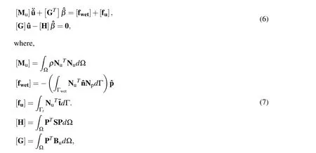
where S=C−1the compliance matrix.

Now using harmonic solution we get,


2.2 FEM formulation for the fluid domain and coupling with structural mechanics
The fluid domain is modelled using the linearized Reynolds equation for squeeze film as follows,

whereµeff,h0,Paare the effective viscosity,the initial air gap and the ambient air pressure respectively.Pis the perturbed fluid pressure aboutPa,andHis the perturbed air gap abouth0.The last term in the above equation signifies the coupling between the fluid and the structural domains.


Now considering‘pδ’as the variation in‘˜p’,and following the procedure outlined in[Roychowdhury,Nandy,Jog,and Pratap(2013)]we get the weak form of the fluid equation as,

Now using the following interpolations for pressure,its variation and the displacement in the z direction,

and following the procedure outlined in[Roychowdhury,Nandy,Jog,and Pratap(2013)],we arrive at the following discretized form of the fluid equation:


Here in the coupled problem,the two dimensional fluid domain is nothing but the wet surface of the vibrating elastic structure.
Now combining both Eq.17 and Eq.10 we get the coupled element equation for modelling squeeze film effects with structural interaction as follows,

3 Results and Discussions
We now discuss the simulation results for two kinds of 3D elements namely the 27 node brick and the 8 node brick.We compare the results of the displacement based elements with that of the hybrid based elements and try to find the most suitable element for modelling squeeze film geometries.We discuss the accuracy of results as well as efficiency of computation in the two cases.
3.1 Validation and benchmarking
In our prior work[Roychowdhury,Nandy,Jog,and Pratap(2013)]we had validated our coupled formulation with experimental data from literature and with analytical expressions.Here we set a benchmark mesh for comparing the results obtained from other mesh sizes for both the 27 node and the 8 node elements.We use a very fine 27 node hybrid element mesh(no.of elements=2400(Nx=100,Ny=6,Nz=4),number of nodes=23517,degrees of freedom=94068)as our benchmark mesh.Table 1 shows the quality factors for the first three modes of a cantilever computed with the benchmark 27 node hybrid mesh and the corresponding values of the experimentally reported quality factors and natural frequencies from Pandey and Pratap(2007).
The cantilever modelled is of length 350µm,width 22µm and thickness 4µm,having an air gap of 1.4µm.The cantilever is made of polysilicon.The relevant mechanical properties of polysilicon used in the simulations are[Pandey and Pratap(2007)],ρSi=2330 Kg/m3as density,ESi=160 GPa as Young’s modulus,andν=0.22 as Poisson’s ratio.The fluid medium considered is air,with properties as follows;ρair=1.2 Kg/m3as density,andµ=1.8×10⁻⁵N-s/m2as viscosity.In the discussions to follow we will use the benchmark mesh to compare with other mesh sizes for both the 27 node as well as the 8 node simulation results,we also use this same cantilever dimensions for all the mesh sizes compared.Figure 2 shows a 27 node Mesh(Nx=7,Ny=2,Nz=1).

Table 1:Comparison of the computed Q factor from the benchmark mesh with the experimentally reported values.
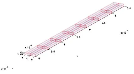
Figure 2:27 Node mesh(Nx=7,Ny=2,Nz=1)
3.2 Comparison between hybrid and displacement based formulations for linear elements
We first compare the performance of the hybrid formulation vis a vis the displacement based(conventional)formulation for linear elements,i.e.,the 8 node brick elements.We model the same benchmark cantilever as discussed in the previous section and plot the percentage error in the tip displacement for different mesh sizes for a frequency of 1 kHz.The error is computed with respect to the tip displacement value obtained with the benchmark mesh using 27 node hybrid elements.Figure 3 shows the percentage error in the computed tip displacement of the cantilever for the two elements.We find from Fig.3 that the hybrid element shows less than 1%error with respect to the benchmark mesh,as opposed to large error percentages for the corresponding displacement based element.We also note that the convergence for hybrid elements is much quicker,and the hybrid element converges at moderate mesh sizes compared to the displacement based elements.
Thus for modelling squeeze film geometries where one is limited to using linear elements(say due to the limitations in mesh generator or otherwise)a hybrid formulation shows much faster convergence and greater accuracy than its displacement based counterpart,and is therefore a better choice for modelling squeeze film geometries.
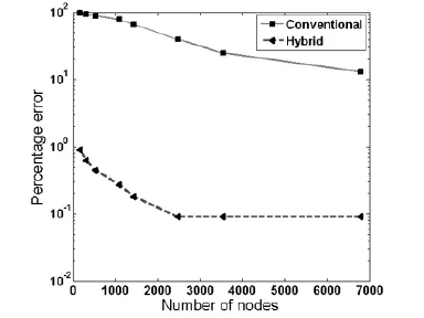
Figure 3:Convergence of computed tip displacement and the corresponding errors for 8 noded conventional(displacement based)and hybrid elements
3.3 Performance study of 8 node hybrid element
In the previous section we saw that the hybrid linear element is much superior to its displacement based counterpart in terms of accuracy and convergence.In this section we investigate how efficient the 8 node hybrid element is in modelling squeeze film parameters,namely the Q factor.We compute the first three Q factors for our benchmark cantilever and plot the percentage error in the computed Q,against our benchmark 27 node hybrid mesh.The first three Q factors correspond to the first three modes of the benchmark cantilever with corresponding natural frequencies as 43 kHz,245 kHz and 690 kHz respectively.
From Table 2 we see that the 8 node hybrid formulation results in convergence for all the Q factors at moderate mesh sizes.We also note that with very fine meshes for the 8 node hybrid the results converge towards the benchmark 27 node hybrid mesh values.We further note that hybrid elements give results within 5%of the benchmark values for moderate mesh sizes(Nx=30,Ny=6,Nz=4)for Q1.For meshes finer than(Nx=60,Ny=12,Nz=4)the 8 node hybrid elements give results within 1%of the more accurate and computationally intensive 27 node benchmark mesh results for Q1.
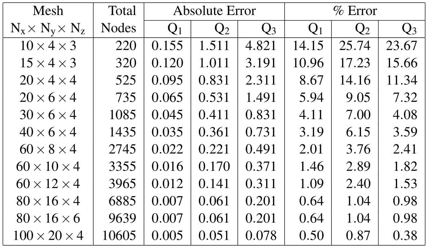
Table 2:Percentage and absolute errors in Q factors computed with 8 node hybrid elements with progressive mesh refinement.The error is computed with respect to the 27 node benchmark mesh.
3.4 Comparison between hybrid and conventional 27 node elements
In this section we try to determine how effective a hybrid formulation is in terms of accuracy and convergence,when compared to the conventional 27 node formulation.We also do a performance study and compare the accuracies of the two formulations at high and low mesh refinements.Table 3 shows the percentage errors in Q factor computed for the first three modes of the benchmark cantilever using 27 node conventional and hybrid elements.The hybrid 27 node elements perform well at low and moderate mesh sizes,and perform slightly better than the conventional element at higher mesh sizes.We also see that at very fine mesh sizes the conventional 27 node mesh values are similar to the hybrid 27 node mesh values.We note from Table 3 that even for very coarse meshes the high frequency Q factor is within 30%of the benchmark value,whereas for the conventional formulation the error is>200%at the same mesh refinement.We see from Table 3 That the hybrid elements show less than 5%error with as coarse a mesh as(Nx=7,Ny=2,Nz=1)for all the three Q factor values.Thus we find the hybrid 27 node element to outperform its conventional counterpart at lower mesh sizes.At higher mesh refinement levels the difference between the two is not so pronounced.

Table 3:Percentage errors in Q factors computed with 27 node conventional(Qi−c)and 27 node hybrid(Qi−h)elements as compared to the benchmark mesh
3.5 Computational cost study
We have seen that the hybrid 27 node element shows great accuracy even at coarse mesh sizes.We now see how the 27 node hybrid element compares with the three other element types discussed as far as computational cost is concerned.For this purpose we compare results for coarse,medium and fine meshes for the same number of nodes for all the elements.Again we tabulate the percentage error(see Table 4)in the computed first three Q factors against our benchmark mesh for the 8 and 27 node hybrid and conventional formulation for three different mesh refinements.For each mesh refinement,we have chosen an appropriate number of elements,for both the 8 and the 27 node formulations so as to have the same degrees of freedom for a true comparative performance study.
We see from Table 4 that for all levels of mesh refinement the 8 node hybrid elementismore accurate when compared to itsdisplacementbased counterpart.For the case of27 node elements the hybrid elementoutperformsits displacementbased counterpart(specially at high frequencies,i.e.,Q3computation).However,for more refined meshes the displacement based 27 node element performs comparably to the hybrid counterpart.
We now look at the computational cost with respect to accuracy for equivalent meshes among the four element types discussed.We present in Table 5 the computational times(using a machine with Intel i5-2500 CPU@3.30 GHz and 20 GB RAM)for a run of 50 frequencies for the mesh sizes discussed in Table 4.The percentage errors in computing the high frequency(Q3)quality factor are presented alongside the computational time in seconds for the mesh sizes under discussion.For a relatively coarse mesh(Nx=7,Ny=2,Nz=1)the computational times(See Table 5)for27 node hybrid and 27 node conventionalelementsare similar;however the hybrid element even at such a coarse mesh comes to within 5%of benchmark values for all the three computed quality factors(Refer Table 4).At fine mesh(Nx=15,Ny=3,Nz=2)the accuracy of the 27 node hybrid is comparable to its conventional counterpart at low frequencies and slightly better at higher frequencies.However the computational cost for the hybrid 27 node at fine mesh size is much higher than the equivalent conventional 27 node mesh.
Thus for the current problem the conventional 27 node compares at par with its hybrid counterpart for refined mesh sizes,and at a lesser cost.For coarse meshes the hybrid element is more efficient considering both accuracy and cost for all frequencies.If however,one were to consider locking effects due to curvature in geometry(as shown in example 3C,Table 1,in the reference[Jog(2010)])the hybrid 27 node performs much better than the conventional 27 node elements and the additional cost of computation of using hybrid formulation may be well justified.It is however,clear from the data that for reasonably high accuracy and lower computational cost,the 27 node conventional element is a good choice.
Considering the case of the linear elements,the 8 node hybrid element greatly outperforms its conventional counterpart at all frequencies with a slightly higher computational cost in each case.Thus for the scenarios where one is limited to using linear elements(say due to mesh generator limitations)the 8 node hybrid element is a better choice for modelling squeeze film geometries.
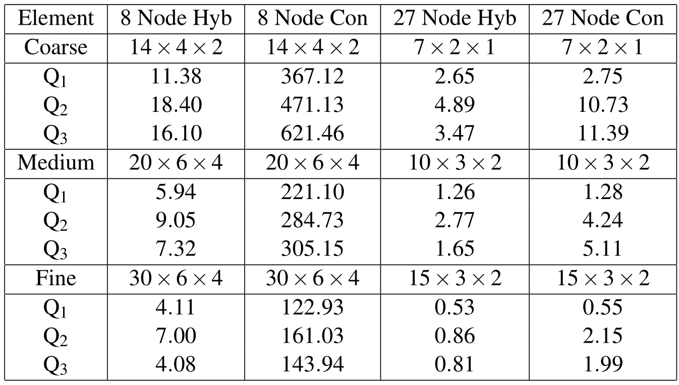
Table 4:Equivalent mesh study:percentage errors in computed Q factors
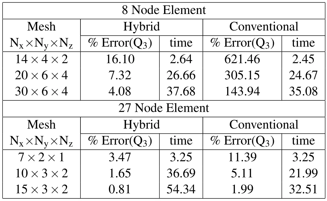
Table 5:Comparative cost(time in seconds forrun of50 frequencies)and efficiency study across 8 node and 27 node equivalent meshes for both hybrid and linear elements
3.6 Varying aspect ratio study
We studied the variation of element aspect ratio on the computed Quality factor for the firstmode ofvibration forboth 8 node hybrid and 8 node conventionalelements.For this study we again chose to model the benchmark cantilever with dimensions and material properties as mentioned in section 3.1.We vary the element aspect ratio(element length to element thickness ratio)by varying the number of elements along the length direction,and fixing the number of elements along the width and the thickness(z direction)at a moderate value.The percentage errors in the first Q factor for both the hybrid and the conventional elements for varying aspect ratio for the corresponding mesh sizes are presented in Table 6.
We find that the hybrid formulation is able to handle higher element aspect ratios(thus lower mesh sizes)with reasonable levels of accuracy.We see that even for element aspect ratios above 10(Nx=30,Ny=6,Nz=4)the error in computing the first Q factor is<5%compared to benchmark,when using hybrid elements.However using conventional elements,even a relatively large mesh(Nx=100,Ny=6,Nz=4)and much lower element aspect ratio still results in error values>20%,when compared to benchmark(we note that the width direction has been kept constant in this study that is why the convergence trend is different from Table 2).Thus the lower order conventional elements are not suitable for modelling high element aspect ratio geometries as found in MEMS structures showing squeeze film effects.
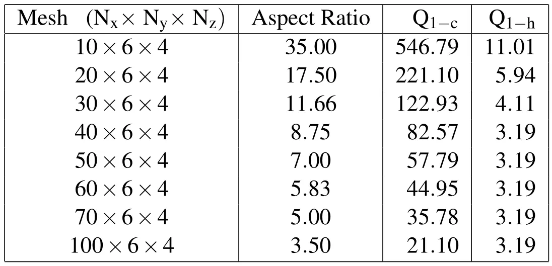
Table 6:Percentage errorsforfirstmode Qfactors forvarying elementaspectratios,computed with 8 node conventional(Q1−c)and 8 node hybrid(Q1−h)elements as compared to the benchmark mesh
4 Conclusions
In this study we have discussed the implementation of a hybrid finite element formulation for coupled squeeze film modelling in MEMS devices.We have developed both hybrid 8 node as well as hybrid 27 node elements for modelling squeeze film geometries.We have compared their performance to their corresponding displacement based counterparts.We find that the hybrid elements outperform the displacement based elements signi ficantly specially at coarse mesh sizes.This is primarily due to the fact that the hybrid elements are able to handle geometries that have unfavourable aspect ratios(i.e.,very thin plate elements).The effect of element aspect ratios for hybrid and conventional formulations have been compared for 8 node elements and we have shown that the hybrid formulation handles steeper aspect ratios favourably compared to the conventional formulation.Even for the superior 27 node elements we have shown that the hybrid formulation for a very coarse mesh(Nx=7,Ny=2,Nz=1)comes to within 5%of the benchmark mesh results.
We also find that the hybrid elements perform very well for high frequency modelling(accuracy of computingQ3).We have studied equivalent meshes for both 8 and 27 node hybrid as well as conventional elements and discussed their efficiency.We have considered both computational cost as well as accuracy with respect to bench mark values for all the element types.We find that the 27 node hybrid element is an optimal choice when moderate accuracy levels are required(thus coarse meshes maybe employed which result in accuracy within 5%of benchmark).For fine meshes the 27 node conventional element proves to be a more optimal choice after considering both cost and accuracy.For the linear 8 node elements the hybrid formulation is seen to outperform the conventional elements greatly for low as well as high frequency computations,and involves only a marginally higher computational cost than the 8 node conventional element.
Acknowledgement:This work is partially supported by NPMASS grant for computational micro-systems.The authors acknowledge the support from Computational Nano Engineering Lab of the Center for Nano Science and Engineering at The Indian Institute of Science.
Atluri,S.N.(1975): On ‘hybrid’finite element models in solid mechanics.In Vichnevetsky,R.(Ed):Advances in Computer Methods for Partial Differential Equations,pp.346–356.AICA,Rutgers University(U.S.A)/University of Ghent(Belgium).
Atluri,S.N.(1984): Alternate stress and conjugate strain measures and mixed variational formulations involving rigid rotations,for computational analyses of finitely deformed solids,with applications to plates and shells-I.Computers and Structures,vol.18,no.1,pp.93–116.
Atluri,S.N.;Han,Z.D.;Rajendran,A.(2004):A New Implementation of the Meshless Finite Volume Method,Through the MLPG"Mixed"Approach.CMES:Computer Modeling in Engineering&Sciences,vol.6,no.6,pp.491–513.
Bao,M.;Yang,H.(2007):Squeeze Film Air Damping in MEMS.Sensors and Actuators A:Physical,vol.136,no.1,pp.3–27.
Bishay,P.L.;Atluri,S.N.(2012): High-Performance 3D Hybrid/Mixed,and Simple 3D Voronoi Cell Finite Elements,for Macro-and Micro-mechanical Modeling of Solids,Without Using Multi-field Variational Principles.CMES:Computer Modeling in Engineering&Sciences,vol.84,no.1,pp.41–97.
Blech,J.J.(1983):On Isothermal Squeeze films.Journal of Lubrication Technology,vol.105,no.4,pp.615–620.
Brezzi,F.(1974):On the existence,uniqueness and approximation of saddle-point problems arising from lagrangian multipliers.Revue francaise d’automatique,informatique,recherche operationnelle.Analyse numerique,vol.8,no.R2,pp.129–151.
Darling,R.B.;Hivick,C.;Xu,J.(1997): Compact Analytical Models for Squeeze Film Damping with Abitrary Venting Conditions.International Conference on Solid State Sensors and Actuators,vol.2,pp.1113–1116.
Dong,L.;Atluri,S.N.(2011): A Simple Procedure to Develop Efficient&Stable Hybrid/Mixed Elements,and Voronoi Cell Finite Elements for Macro-&Micromechanics.CMC:Computers Materials and Continua,vol.24,no.1,pp.61–104.
Dong,L.;Ei-Gizawy,A.S.;Juhany,K.A.;Atluri,S.N.(2014a): A Simple Locking-Alleviated 4-Node Mixed-Collocation Finite Element with Over-Integration,for Homogeneous or Functionally-Graded or Thick-Section Laminated Composite Beams.CMC:Computers Materials and Continua,vol.40,no.1,pp.49–77.
Dong,L.;Ei-Gizawy,A.S.;Juhany,K.A.;Atluri,S.N.(2014b): A Simple Locking-Alleviated 3D 8-Node Mixed-Collocation C 0 Finite Element with Over-Integration,forFunctionally-Graded and Laminated Thick-Section Plates and Shells,with&without Z-Pins.CMC:Computers Materials and Continua,vol.41,no.3,pp.163–192.
Hannot,S.;Rixen,D.J.(2009): Coupling Plate Deformation,Electrostatic Actuation and Squeeze Film Damping in a FEM Model of a Micro Switch.International Conference on Computational Methods for Coupled Problems in Science and Engineering,Barcelona,pp.1–4.
Jog,C.S.(2005):A 27-node hybrid brick and a 21-node hybrid wedge element for structural analysis.Finite Elements in Analysis and Design,vol.41,no.11–12,pp.1209–1232.
Jog,C.S.(2010):Improved hybrid elements for structural analysis.Journal of Mechanics of Materials and Structures,vol.5,no.3,pp.507–528.
Li,P.;Hu,R.;Fang,Y.(2007): A new model for squeeze-film damping of electrically actuated microbeams under the effect of a static deflection.Journal of Micromechanics and Microengineering,vol.17,no.7,pp.1242–1251.
McCarthy,B.;Adams,G.G.;McGruer,N.E.;Potter,D.(2002):A Dynamic Model,Including Contact Bounce,of an Electrostatically Actuated Microswitch.Journal of Microelectromechanical Systems,vol.11,no.3,pp.276–283.
Pandey,A.K.;Pratap,R.(2007): Effect of Flexural Modes on Squeeze Film Damping in MEMS Cantilever Resonators.Journal of Micromechanics and Microengineering,vol.17,no.12,pp.2475–2484.
Pian,T.H.H.;Sumihara,K.(1984):Rational approach for assumed stress finite elements.International Journal for Numerical Methods in Engineering,vol.20,no.9,pp.1685–1695.
Pian,T.H.H.;Tong,P.(1986): Relations between incompatible displacement model and hybrid stress model.International Journal for Numerical Methods in Engineering,vol.22,no.1,pp.173–181.
Pratap,R.;Mohite,S.;Pandey,A.K.(2007):Squeeze Film Effects in MEMS Devices.Journal of the Indian Institute of Science,vol.87,no.1,pp.75–94.
Pratap,R.;Roychowdhury,A.(2014):Vibratory mems and squeeze film effects.In Vinoy,K.J.;Ananthasuresh,G.K.;Pratap,R.;Krupanidhi,S.B.(Eds):Micro and Smart Devices and Systems,Springer Tracts in Mechanical Engineering,pp.319–338.Springer India.
Punch,E.F.;Atluri,S.N.(1984):Development and testing of stable,invariant,isoparametric curvilinear 2D and 3D hybrid-stress elements.Computer Methods in Applied Mechanics and Engineering,vol.47,pp.331–356.
Roychowdhury,A.;Nandy,A.;Jog,C.;Pratap,R.(2013):AMonolithic,FEM-based Approach for the coupled Squeeze Film Problem of an Oscillating Elastic Micro-Plate Using 3D 27-Node Elements.Journal of Applied Mathematics and Physics,vol.1,no.6,pp.20–25.
Rubinstein,R.;Punch,E.F.;Atluri,S.N.(1983):An analysis of,and remedies for,kinematic modes in hybrid-stress finite elements:selection of stable,invariant stress fields.Computer Methods in Applied Mechanics and Engineering,vol.38,pp.63–92.
Xue,W.M.;Karlovitz,L.A.;Atluri,S.N.(1985): On the existence and stability conditions for mixed-hybrid finite element solutions based on Reissner’s variational principle.International Journal of Solids and Structures,vol.21,no.1,pp.97–116.

