
Numerical Simulation of Oxy-coal Combustion for a Swirl Burner with EDC Model*
2014-03-25 09:11:24崔凯刘冰吴玉新杨海瑞吕俊复张海
(崔凯)(刘冰)(吴玉新)(杨海瑞)(吕俊复)(张海)**
Key Laboratory for Thermal Science and Power Engineering of Ministry Education, Department of Thermal Engineering, Tsinghua University, Beijing 100084, China
Numerical Simulation of Oxy-coal Combustion for a Swirl Burner with EDC Model*
CUI Kai(崔凯), LIU Bing(刘冰), WU Yuxin(吴玉新), YANG Hairui(杨海瑞), LÜ Junfu(吕俊复)and ZHANG Hai(张海)**
Key Laboratory for Thermal Science and Power Engineering of Ministry Education, Department of Thermal Engineering, Tsinghua University, Beijing 100084, China
The characteristics of oxy-coal combustion for a swirl burner with a specially designed preheating chamber are studied numerically. In order to increase the accuracy in the prediction of flame temperature and ignition position, eddy dissipation concept (EDC) model with a skeletal chemical reaction mechanism was adopted to describe the combustion of volatile matter. Simulation was conducted under six oxidant stream conditions with different O2/N2/CO2molar ratios: 21/79/0, 30/70/0, 50/50/0, 21/0/79, 30/0/70 and 50/0/50. Results showed that O2enrichment in the primary oxidant stream is in favor of combustion stabilization, acceleration of ignition and increase of maximum flame temperature, while the full substitution of N2by CO2in the oxidant stream delays ignition and decreases the maximum flame temperature. However, the overall flow field and flame shapes in these cases are very similar at the same flow rate of the primary oxidant stream. Combustion characteristics of the air-coal is similar to that of the oxy-coal with 30% O2and 70% CO2in the oxidant stream, indicating that the rear condition is suitable for retrofitting an air-coal fired boiler to an oxy-coal one. The swirl burner with a specially designed preheating chamber can increase flame temperature, accelerate ignition and enhance burning intensity of pulverized coal under oxy-coal combustion. Also, qualitative experimental validation indicated the burner can reduce the overall NOχemission under certain O2enrichment and oxy-coal combustion conditions against the air-coal combustion.
oxy-coal, eddy dissipation concept model, coal, swirl burner
1 INTRODUCTION
Conventional pulverized coal boilers use air as oxidant and thus the flue gas is mainly consisted of nitrogen (N2) and carbon dioxide (CO2) while CO2is less than 20% in volume. The capture of CO2from such dilute mixtures using amine stripping or other techniques is expensive. In oxy-coal combustion, oxygen (O2), typically of greater than 95% purity, is used as the oxidant, and CO2concentration in the flue gas can be over 90%. However, for flame temperature control, CO2dilution into the oxidizer stream is necessary [1, 2]. Such a manner could delay the ignition and affect combustion process of pulverized coals. Thus, burners with high performance in ignition and combustion are still demanded for oxy-coal combustion.
In our previous studies [3, 4], a high temperature air combustion (HTAC) burner was designed. The burner, as shown in Fig. 1, is specially equipped with a preheating chamber and the pulverized coal-containing primary air stream enters the chamber from an off-centre duct. With such a structure, internal high temperature flue gas recirculation can be established in the chamber.Experiments and applications showed that the HTAC burner possesses excellent performance in combustion stabilization, low NOχemission, and is capable to burn low volatile content (LVC) coals [3, 4]
Figure 1 Schematic of the swirl type HTAC burner with a special preheating chamber
In this paper, oxy-coal combustion with the HTAC burner at different O2concentrations was numerically studied and eddy dissipation concept (EDC) model with a skeletal chemical reaction mechanism was adopted to describe the combustion of volatile matter. The results were compared with that of air combustion. Simulation was also conducted for the O2-enriched air combustion in which N2in the air stream was partially replaced by O2such that the O2concentration in the oxidant stream was higher than 21%. The maximum flame temperature and flame temperature contour were examined to assess the feasibility of boiler retrofit from air-fuel combustion to oxy-fuel combustion with the minimal cost.
2 NUMERICAL SIMULATION
The numerical simulation was based on an Eulerian-Lagrangian formulation of the 3D gas-solid two phase flow, using the commercial CFD code FLEUNT 6.3. The gas phase conservation equations were solved in Eulerian frame and solid phase were solved in Lagrangian frame, and the coupling between two phases was done through interactive source terms. Finite volume pressure-based solver with implicit linearization was used. The SIMPLE algorithm was used for pressure-velocity coupling. The space derivatives of the diffusion terms were discretized by the central differencing scheme, and the stiff non-linear terms were discretized by the first order scheme.
The sub-models for turbulent flow, radiation, particle tracking, devolatilization, volatile matter combustion, char combustion are introduced as follows.
2.1 Model for turbulent flow
Several two-equation eddy viscosity turbulence models and Reynolds stress model (RSM) were tested during the model selection for the combustion of pulverized coal. The comparison between simulation results and experimental data showed RSM has good performance in the predictive precision and stability of convergence, though with a slightly more CPU cost [5]. Thus, RSM was used for the turbulent flow, and standard wall-function is applied to resolve near-wall region.
2.2 Model for radiation
There are two most commonly used radiation models for particle radiation, namely P1 model [6, 7] and discrete ordinates (DO) model [8, 9]. Due to its better accuracy, DO method was chosen in spite of higher computing cost. Weighted sum of gray gases model [10] was chosen to calculate the fluid absorption coefficients.
2.3 Model for particle tracking
The status and position of coal particles were tracked in the Lagrangian frame. The size of coal particles was assumed to satisfy the Rosin-Rammler distribution. Based on the distribution, the coal particle size was divided into 10 intervals, in which the size of the particles was represented by their averaged value. Then, in each cell on the injection plane, the particles with the same size were evenly divided in number into 3 groups. The totally number of groups of coal particles were ~12000. In each group, the particles were regarded to have same velocity, temperature and other status, behaving the same way. The composition and burning rate of particles of each group change, but its size remains at the initial one. Such a treatment greatly reduced the computational cost and improved the convergence. The trajectory of a discrete phase particle was predicted by integrating the forces subjecting to the particles. No interaction was considered between the particle groups, while the interactions between the discrete phase with the continuous phase through mass, momentum, energy and species sources were considered. In the simulation, the equations for continuous phase and discrete phase were alternatively solved until solutions of both phases converge. To ensure the convergence for the continuous phase, 200-300 continuous phase iterations were done per discrete phase iteration. The dispersion of particles due to turbulence in the fluid phase was predicted by the stochastic tracking model.
2.4 Model for volatile matter combustion
In order to increase the accuracy in predicting flame temperature and ignition position, the EDC model with a skeletal chemical reaction mechanism was applied to describe the combustion of volatile matter. The skeletal mechanism included 16 species and 41 reactions, which was used to model CH4/air turbulent combustion by Yang and Pope [11]. This model could avoid the over-prediction of temperature and premature ignition, which were caused by fast reaction assumption and missing of intermediate species in eddy dissipation (ED) model and mixture fraction/PDF (possibility density function) model. In the framework of FLUENT, an UDF (user defined function) code was compiled to implement the above features used in EDC model, based on the suggestion from Byggstoyl and Magnussen [12] and Gran et al [13].
The EDC model was developed by Magnussen and Hjertager [14] in 1976 to include chemical mechanisms in turbulent reacting flows, based on eddy dissipation turbulence energy cascade model [15], sometimes called simply eddy cascade model. The cascade model connects the viscous fine structures at which combustion takes place, and the larger transporting eddies, and expresses fine-structure quantities in terms of turbulence energy and dissipation. The scales of turbulence are assumed to be continuously distributed over a wide time and space spectrum. Mechanical energyis transferred from the main flow to large eddies and then further to smaller eddies. The larger eddies carry the most kinetic energy. Smaller eddies whirl faster but carry less energy. The smallest eddies have the highest frequency and the largest viscous stresses. Viscous friction transfers mechanical energy to heat which is then dissipated. The smallest eddy has a length scale called Kolmogorov length scale. If the eddy size is smaller than this scale, no turbulent structure exists. Based on this idea, the concept of the EDC was developed: There is a region in which the reactants can be regarded as ideally mixed and thus chemical reaction kinetics determines the rate of the process, while outside this region the reactants are not mixed and do not react. Therefore, each computing cell is separated into two regions: reaction region and inert region, and separately called as fine-scale structure and surroundings. Fine-scale structure is the smallest eddy, whose dimensions are small in one or two directions, however not in all three. These fine structures have the characteristic dimension in the same magnitude as Kolmogorov microscale, and mainly located in the highly strained regions between larger energy-rich eddies [16].
EDC model has been widely used in gas combustion simulation [17-19] but was not reported for coal combustion with detailed, skeletal or reduced chemistry for volatile matter (VM) combustion. In the present study, EDC model was integrated with other models in FLUENT software with a skeletal chemistry for VM combustion and it is expected that it can increase the accuracy in prediction of flame temperature and ignition position.
When EDC model with the skeletal chemical reaction mechanism is applied, the number of iteration of direct integration is huge. To reduce the CPU cost, an in-situ adaptive tabulation (ISAT) procedure that was proved to have 100-1000 times speed-up in PDF modeling of a turbulent reacting flow by Pope [20] was adopted in this study.
2.5 Definition of volatile matter
Although great efforts have been paid by many researchers, so far there is no a clear, convictive and popularly accepted way to define the volatile matter (VM) as it is difficult to precisely mimic the practical combustion environment and measure the species of volatile matter in experiments. According to the suggestions in [21-23], the light gases CH4, H2and CO were regarded as the main VM species. Their molar ratios for the coal used were defined as 35︰43︰22, based on the criterion that the elemental mass should be consistent with the ultimate analyses and total heat released should be the same as the higher heating value from the proximate analysis.
2.6 Model for devolatilization
Currently, there are several commonly used models to describe volatile matter releases, including the first-order reaction model, two-competing model and macromolecular network models [24-31]. Since the main target of the paper is to study oxy-coal combustion characteristic with the HTAC burner at different O2concentrations, the rather complicated macromolecular network model was not necessary and the two-competing model [31] was chosen. The model can be expressed as follows:
where R1and R2are competing kinetic rates controlling the devolatilization over different temperature ranges; mv(t) is volatile yield up to time t, kg; mp,0is initial particle mass, kg; α1and α2equal to 0.3 and 1.0 respectively; mais ash content in the particle, kg; fw,0is the initial moisture fraction of the particle.
The two kinetic rates are expressed in the Arrhenius form as
According to Ref. [31], A1and E1are set to 2.0×10⁵s−1and 1.04×10⁸J·mol−1respectively; A2and E2are set to 1.3×10⁷s−1and 1.67×10⁸J·mol−1respectively (built-in parameters in Fluent 6.3).
2.7 Model for char surface combustion
The kinetic/diffusion surface reaction rate model [32] was applied to describe char combustion, assuming that the surface rate of particle was determined either by kinetics of surface reaction or by diffusion rate of oxygen. The model can be represented by
where ρ is the density of char, kg·m−3; Apis the area of particle surface, m2; R is the universal gas constant, J·mol−1·K−1; T∞is gas temperature, K; Yoxis the oxidant mass fraction; Mw,oxis the molecular mass of oxidant, kg·kmol−1. Rdiffis the diffusion reaction rate coefficient and Rcis the kinetic or chemical reaction rate coefficient. Rdiffand Rcare expressed as
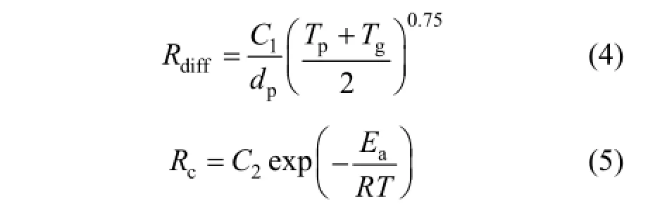
where dpis the diameter of the particle, m; Tpis the temperature of particle, K; Tgis the surrounding gas temperature K; Eais the reaction activation energy, J·kg−1·mol−1, C1is mass diffusion-limited rate constantand C2is the kinetics-limited rate pre-exponential factor. The constants C1, C2and Ea are 5×10⁻¹²kg·s−1, 0.002 kg·s−1and 7.9×10⁷J·mol−1respectively [32].
利用Design-Expert 8.0.6进行Box-Behnken实验的设计,设计因素及对应水平如表2所示。
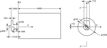
Figure 2 The structure and dimensions of burner and furnace used in simulation (unit: mm)
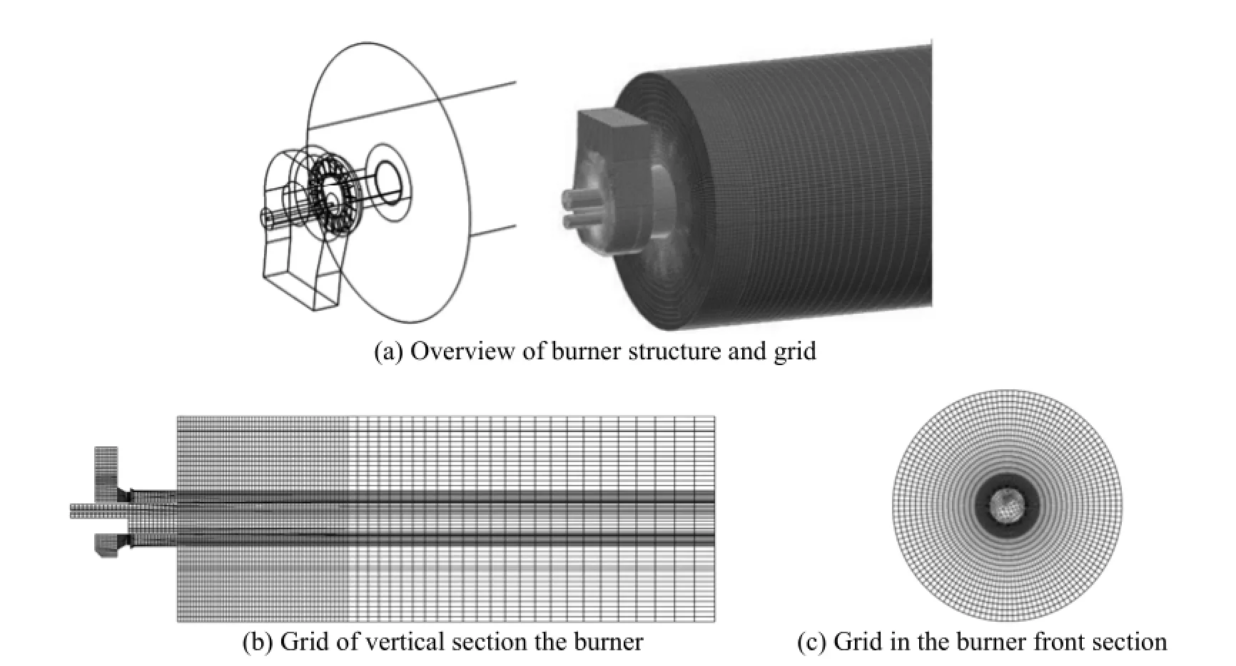
Figure 3 The geometry and girds of burner
2.8 Structure and grid
The structure and dimensions of the burner and furnace used in the simulation are shown in Fig. 2. The secondary air vane angle was 60°.
The hexahedral type grid was used to mesh the computational domain, as shown in Fig. 3. This type of grid not only was more stable to convergence, but also needed much less mesh number than other types of grids. A grid independence check for Case 1 was performed in order to properly set the gird number. First, stable solutions were obtained under the same condition but with different grid numbers. Then, a monitoring point was selected and the temperature difference between this point and the primary air inlet were calculated. When the temperature difference was nearly independent with the grid number, the solution was regarded to be independent of grid number. In the present study, a monitoring point was located on the centerline of the furnace and 50 cm away from the burner exit. Shown in Fig. 4, the temperature difference became nearly unchanged (with relative errorwithin 1%) when the grid number was larger than 35000, indicating that further increasing the grid number would not increase the predictive accuracy. Accordingly, the grid number of 40000 was used for Case 1. Due to the similarity in numerical simulation, this gird number was applied to other cases too.
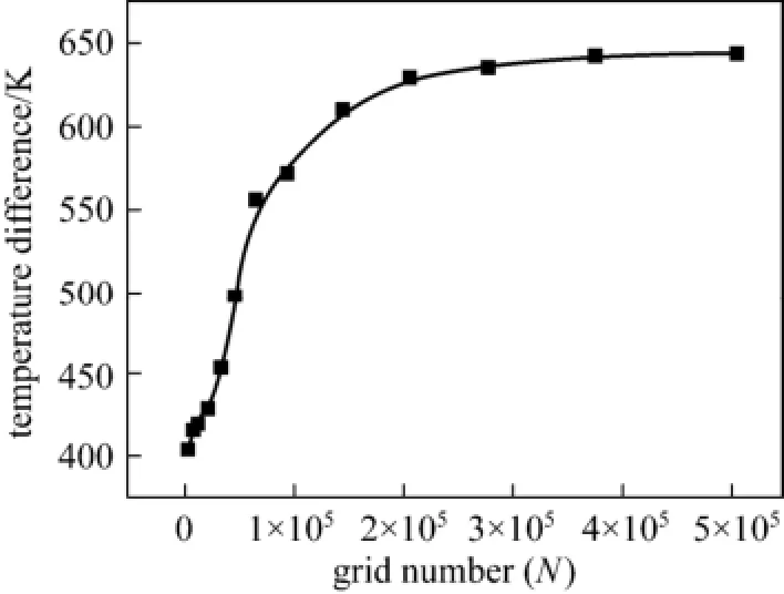
Figure 4 Grid independence check for Case 1
2.9 Coal properties and operational parameters
The proximate and ultimate analyses of the lean coal used in simulation are listed in Table 1. The main operational parameters of the burner are given in Table 2. The primary air was in atmospheric pressure, but at a temperature of 573 K. The excess air ratio was remained at ~1.2 for all cases and correspondingly the mass flows of primary and secondary air were adjusted at different O2and CO2concentrations. In the present study, six cases with different compositions and mass flow rates of the primary and secondary airs as listed in Table 3 were simulated.
3 RESULTS AND DISCUSSION
3.1 Effect of O2concentration in the primary air on overall flow
As O2increase in the primary air flow, the secondary air flow rate and thus the overall flow rate of reacting gas decreases in some extent, as exemplified by Cases 1 to 3 in Table 3. It is then interesting to check if this will cause significant changes in the overall flow field. Simulation showed that the velocity fields of six cases are very similar, and the representative velocity field is displayed in Fig. 5. Four reverse flowzones exist in the area adjacent to the burner including one in the preheating chamber, one outside the burner caused by swirl secondary air and two side-wall reverse flow zones. The reverse flow in the preheating chamber entrains hot flue gas from the furnace to preheat the primary air, and thus is beneficial to flame stabilization.
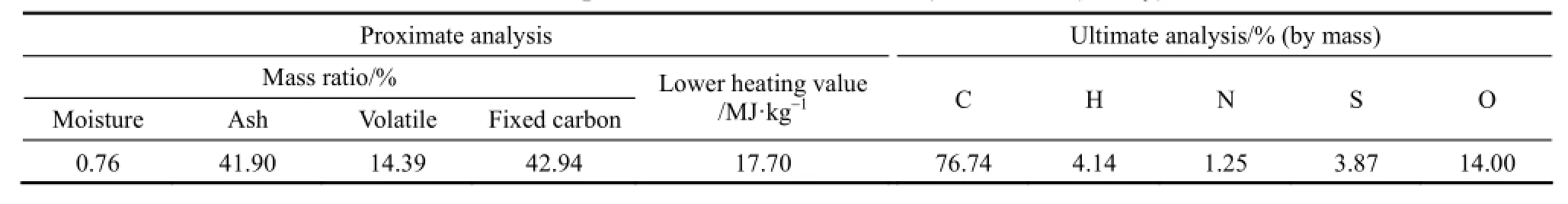
Table 1 The proximate and ultimate analyses of coal (air dry)
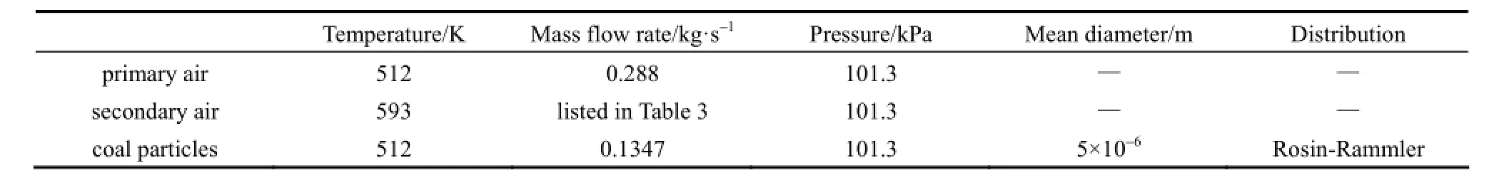
Table 2 Operational parameters and conditions used in simulation
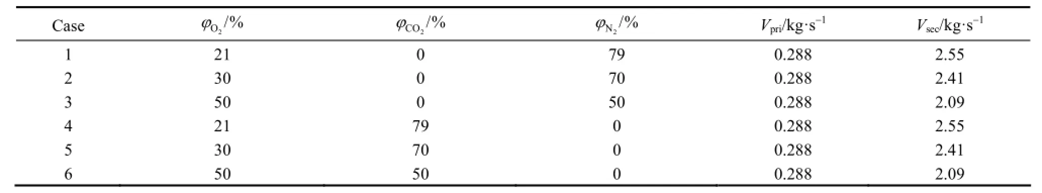
Table 3 Composition and mass flow rate for the primary and secondary air
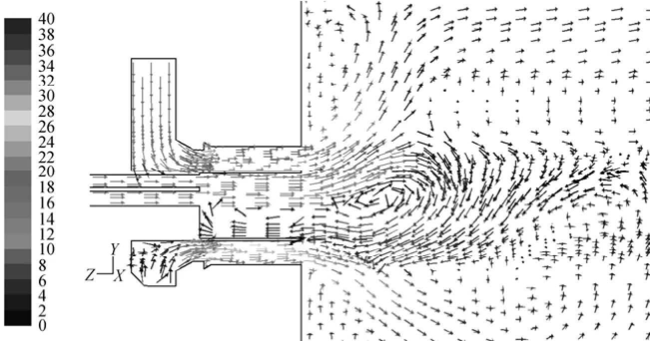
Figure 5 Typical map of velocity vector of HTAC burner (Case 1)
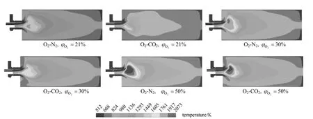
Figure 6 Temperature fields with different O2/N2/CO2composition in the oxidant stream
3.2 Effect of primary air composition on temperature field
The predicted results of the temperature field with six O2/N2/CO2compositions in the oxidant stream are respectively shown in Fig. 6. Due to the offset of the primary gas stream, the temperature field adjacent to the burner is asymmetric and in most cases, flame center locates above the center plane of the burner. Although temperature at the same position varies with inlet gas composition, the flame shapes are similar. The results indicate that difference of the oxidant stream composition has no significant effect on flame shape, though the temperature values are different. This is an interesting phenomenon.
3.3 Effect of primary air composition on the flame temperature
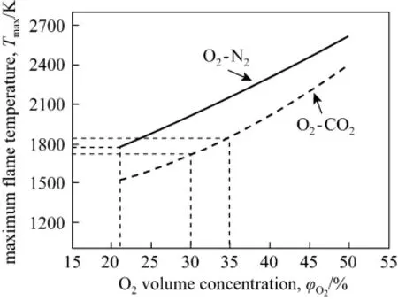
Figure 7 Maximum flame temperatures with different O2/N2/CO2compositions in the oxidant stream
The maximum flame temperature, denoted as Tmax, at different O2, N2and CO2concentrations in the primary oxidizer stream is shown in Fig. 7. It can be seen for both O2-N2and O2-CO2based combustion, Tmaxincreases with O2concentration, while at the same O2concentration, the former one has a higher Tmax. The differential temperature between O2-N2and O2-CO2based combustion is slightly higher at a lower O2concentration and this is because the CO2fraction is correspondingly higher (as shown in Table 3) and thus the average specific heat capacity increases. Consistent with results shown in Fig. 4, to keep Tmaxclose to the one in air based combustion, O2concentration in the oxidant stream should be increased to a value in the range of 30%-35% when oxy-coal combustion is adopted.
The increase of Tmaxin the O2-enriched or oxy-coal combustion could be a concern for the additional NOχformation. On one hand, higher Tmaxdoes increases thermal NOχformation. However, as long as the average temperature in the main combustion zone is less than 1700 K, thermal NOχoccupies only a small fraction of the total NOχin a coal-fired boiler [33]. On the other hand, fuel NOχ, which dominates the total NOχformation in most coal-air combustion, could be remarkably decreased in O2-enriched combustion when the ignition of the coal particles is keptin a reducing environment. In such an environment, O2-enriched combustion enhances the release of fuel-N into volatile-N in high temperature, analogous to the low NOχcombustion feature of HTAC [3, 4]. Thus, the overall NOχformation with for O2-enriched or oxy-coal combustion is not necessarily to increases; instead it could be reduced if combustion is well arranged. The feasibility of overall NOχemission reduction is validated by experiments introduced in the later section.
3.4 Effect of primary air composition on ignition position
So far, there is no unified definition for the ignition position of turbulent coal combustion. In the present study, isothermal curves at 1173 K, that was proposed by a few researchers (e.g., [34]) are chosen to define the ignition position of pulverized coal in the turbulent jet combustion. The numerically defined ignition positions with different O2concentrations in air-coal and oxy-coal combustion are depicted in Fig. 8. With the increase of O2concentration, ignition occurs earlier for both O2-N2and O2-CO2based combustion. In addition, ignition is delayed if N2replaced by CO2in the oxidant stream. The positions at which ignition begins (close to the burner exit) for the cases when=30︰70 and ϕO2︰ ϕCO2=50︰50 is close to that for the air-coal combustion, while the positions at which ignition begins for the cases when= 21︰79 is much delayed than that for the air-coal combustion. The results are mainly attributed to the higher specific heat capacity of CO2and the lower flame temperature in the oxy-coal combustion.
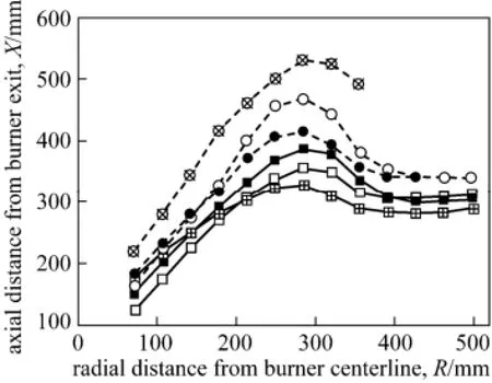
Figure 8 The ignition position under different O2/N2/CO2composition in the oxidant streamO2-CO2,ϕO2= 21%; ○ O2-CO2,ϕO2= 30%; ● O2-CO2, ϕO2= 50%; ■ O2-N2,ϕO2= 21%; □ O2-N2,ϕO2= 30%;O2-N2,ϕO2=50%
3.5 Qualitative experimental validation
Some experiments on the characteristics of O2-enriched air-coal combustion were conducted in a single burner test installation using the swirl burner as simulated. The rated capacity of the burner was about 12 MW in thermal capacity. Several coals including the one used in above simulation were tested, including a lean coal with volatile (Vdaf=14%) and heating value (Qar,net,p=16800 kJ·kg−1) similar to the one used in simulation. The flow rates for the primary air, secondary air and over fire air (OFA, located at about 3.5 m downstream from the burner) were about 0.65 kg·s−1, 2.90 kg·s−1and 0.68 kg·s−1respectively. The coal feed rate was about 0.42 kg·s−1. The overall excess air ratio was about 1.2. All air streams were in ambient temperature. Because of the experimental limitations, the furnace preheated at around 700 K, lower than that of an industrial boiler furnace. During the experiments, in order to save O2consumption, instead of increasing O2concentration of the entire primary air flow, a tube with 25 mm inner diameter was used to supply an O2-enriched O2-N2stream into the preheating chamber. The flow rate of the O2-enriched stream is constant at 9.5×10⁻³kg·s−1, with pure O2stream of 0-3.4×10⁻³kg·s−1balanced by air. A small amount of assistant oil (~20 kg·h−1) was also used since flames were not stable due to the ambient temperature oxidizer streams and the low temperature furnace. NOχmeasurements were conducted at the exhaust section of the flue gas, after combustion remained stable for about 5-10 min.
Though the experimental conditions were not identical to the ones used in the present simulation, the results were still good to qualitatively validate the combustion characteristics and NOχemission performance of the swirl burner. Fig. 9 shows that NOχconcentration in the flue gas decreases about 25% when O2concentration in the O2-enriched stream increases from 21% to 50%. Though at the same time, CO concentration increases about 50% due to the short combustion zone in the experiments, the results are sufficient to validate the hypothesis that O2-enriched or oxy-coal combustion can be an effective way to further decrease rather than increase NOχformation for pulverized coal firing when the proper burner is used. The reduction mechanism is similar to the one in HTAC, that is O2-enriched or oxy-coal combustion can be in favor of the volatile release before coal particles disperse in the oxidizing environment [4, 6].
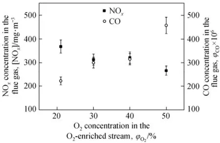
Figure 9 Experimental data on variation of NOxand CO concentration in the flue gas with the O2concentration in the O2-enriched flow
4 CONCLUSIONS
Based on the numerical simulations of oxy-coal combustion in a swirl burner with a specially designed preheating chamber, it was found that there is obvious difference between oxy-coal and air-coal combustion. The substitution of N2with CO2in the same volumetric amount will decrease the maximum flame temperature, and delay ignition of pulverized coal in turbulent stream, but the overall velocity field and flame shapes are similar. When O2concentration increases to 30%, the temperature contour adjacent to the burner is similar to the one in air combustion. The results confirmed that oxy-coal combustion with 30% O2concentration is feasible for retrofitting the existing burner and furnace from air-coal combustion. In addition, eddy dissipation concept model with skeletal chemical reaction mechanism could be adopted to describe the combustion of volatile matter in pulverized coal combustion simulation.
The swirl burner with specially designed preheating chamber is suitable for oxy-coal combustion. The structure of the burner is beneficial to increase flame temperature, accelerate ignition of pulverized coal and enhance combustion. The simulation results and qualitative experimental validation indicated the burner can enhance combustion and further reduce the overall NOχemission under certain O2-enriched and oxy-coal combustion conditions against the air-coal combustion.
NOMENCLATURE
Aparea of particle surface, m2
A1constant (2.0×10⁵s−1)
A2constant (1.3×10⁷s−1)
C1mass diffusion-limited rate constant (5×10⁻¹²kg·s−1)
C2kinetics-limited rate pre-exponential factor (0.002 kg·s−1)
dpdiameter of particle, m
Eachar surface reaction activation energy, J·mol−1
E1, E2activation energy, J·mol−1
fw,0initial moisture content in the particle, %
Mw,oxmolecular mass of oxidant
m mass of char, kg
maash content in the particle, kg
mp,0initial particle mass, kg
mv(t) volatile yield up to time t, kg
R universal gas constant, J·mol−1·K−1
Rckinetic or chemical reaction rate, kg·s−1
Rdiffdiffusion reaction rate, kg·s−1
R1, R2devolatilization rate over different temperature range, kg·s−1
Tp, Tgparticle and gas temperature, K
T∞ambient gas temperature, K
V mass flow rate, kg·s−1
Yoxoxidant mass fraction
α1, α2yield factor
ρ density of char, kg·m−3
φ volume concentration, %
REFERENCES
1 Kakaras, E., Koumanakos, A., Doukelis, A., Glannakopoulos, D., Vorrias, I., “Oxyfuel boiler design in a lignite-fired power plant”, Fuel, 86 (14), 2144-2150 (2007).
2 Shah, M.M., “Oxy-fuel combustion for CO2capture from PC boilers”, In: 31st Intl. Conf. Coal Utilization Fuel System, Coal Technologies Associates, USA, No.3 (2006).
3 Zhang, H., Yue, G.X., Lü, J.F., Zhen, J., Mao, J.X., Fujimori, T., Suko, T., Kiga, T., “Development of high temperature air combustion technology in pulverized fossil fuel fired boilers”, Proc. Combust. Inst., 31, 2779-2785 (2007).
4 Mao, J., Jia, X., Zhang, H., Yue, G.X., Fujimori, T., Suko, T., Kiga, T., “Reducing NOχEmission with PRP Burner for Anthracite fired Boilers”, In: 31st Intl. Technical Conf. on Clean Coal & Fuel Systems, Coal Technologies Associates, USA, No. 21 (2006).
5 Cui, K., Zhang, H., Wang, W.L., Wu, Y.X., Yang, H.R., Lü, J.F.,“Comparison between realizable κ-ε and RSM model in the simulation for a swirl burner”, J. Eng. Thermophys., 33 (11), 2006-2009 (2012). (in Chinese)
6 Cheng, P., “Two-dimensional radiating gas flow by a moment method”, AIAA J., 2, 1662-1664 (1964).
7 Siegel, R., Howell, J.R., Thermal Radiation Heat Transfer, Hemisphere Publishing Corporation, Washington, DC (1992).
8 Chui, E.H., Raithby, G.D., “Computation of radiant heat transfer on a nonorthogonal mesh using the finite-volume method”, Heat Transfer B, 23, 269-288 (1993).
9 Raithby, G.D., Chui, E.H., “A finite-volume method for predicting a radiant heat transfer in enclosures with participating media”, Heat Transfer, 112, 415-423 (1990).
10 Modest, M.F., Radiative Heat Transfer, 2nd edition, Academic Press, London (2003).
11 Yang, B., Pope, S.B., “An investigation of the accuracy of manifold methods and splitting schemes in the computational implementation of combustion chemistry”, Combust. Flame, 112, 16-32 (1998).
12 Byggstoyl, S., Magnussen, B.F., “A model for flame extinction in turbulent low”, Proc. Intl. Symp. Turbulent Shear Flows, 14 (10), 32-38 (1983).
13 Gran, I.R., Melaaen, M.C., Magnussen, B.F., “Numerical simulation of local extinction effects in turbulent combustor flows of methane and air”, Proc. Combust. Inst., 25, 1283-1291 (1994).
14 Magnussen, B.F., Hjertager, B.H., “On mathematical modeling of turbulent combustion with special emphasis on soot formation and combustion”, Proc. Combust. Inst., 16, 719-729 (1976).
15 Ertesvag, I.S., Magnussen, B.F., “The eddy dissipation turbulence energy cascade model”, Combust. Sci. Tech., 159, 213-235 (2000).
16 Magnussen, B.F., “An investigation into the behavior of soot in a turbulent free jet C2H2flame”, Proc. Combust. Inst., 15 (1), 1415-1425 (1975).
17 Crowe, C.T., Sharma, M.P., Stock, D.E., “The particle-source-in cell (PSI-CELL) model for gas-droplet flows”, J. Fluid Eng., 6, 325-332 (1977).
18 Zhang, J.X., “Turbulent diffusion combustion numerical simulation linking EDC combustion model with chemical kinetics reaction mechanism”, Ind. Furnace, 29 (1), 41-44 (2007). (in Chinese)
19 Mi, J.C., Li, P.F., Zheng, C.G., “Numerical simulation of flameless premixed combustion with an annular nozzle in a recuperative furnace”, Chin. J. Chem. Eng., 18 (1), 10-17 (2010).
20 Pope, S.B., “Computationally efficient implementation of combustion chemistry using in situ adaptive tabulation”, Combust. Theory Model., 1, 41-63 (1997).
21 Das, T.K., “Evolution characteristics of gases during pyrolysis of maceral concentrates of Russian coking coals”, Fuel, 80, 489-500 (2001).
22 Fuller, J.E., Coal and Coal Products: Analytical Characterization Techniques, American Chemical Society, Washington, DC (1982).
23 Elliott, M.A., Chemistry of Coal Utilization, Wiley, New York (1981).
24 Howard, J.B., “Fundamentals of coal pyrolysis and hydropyrolysis”, In: Chemistry of Coal Utilization, Elliott, M.A., ed., Willey, New York (1981).
25 Solomon, P.R., Fletcher, T.H., Pugmire, P.J., “Progress in coal pyrolysis”, Fuel, 72, 587-597 (1993).
26 Solomon, P.R., Hamblen, D.G., Carangelo, R.M., Serio, M.A., Deshpande, G.V., “General model of coal devolatilization”, Energy Fuels, 2 (4), 405-422 (1988).
27 Niksa, S., Kerstein, A.R., “The distributed-energy chain model for rapid coal devolatilization kinetics, I: Formulation”, Combust. Flame, 66, 95-109 (1986).
28 Niksa, S., “The distributed-energy chain model for rapid coal devolatilization kinetics, II: Transient weight loss correlations”, Combust. Flame, 66, 111-119 (1986).
29 Niksa, S., Kerstein, A.R., “On the role of macromolecular configuration in rapid coal devolatilization”, Fuel, 66, 1389-1399 (1986).
30 Fletcher, T.H., Kerstein, A.R., Pugmire, R.J., Solum, M., Grant, D.M., “Chemical percolation model for devolatilization. 3. Direct use of carbon-13 NMR data to predict effects of coal type”, Energy Fuel, 6, 414-431 (1992).
31 Kobayashi, H., Howard, J.B., Sarofim, A.F., “Coal devolatilization at high temperatures”, Proc. Combust. Inst., 16, 411-425 (1977).
32 Baum, M.M., Street, P.J., “Predicting the combustion behavior of coal particles”, Combust. Sci. Tech., 3 (5), 231-243 (1971).
33 Bowman, C.T., “Control of combustion-generated nitrogen oxide emissions: Technology driven by regulation”, Proc. Combust. Inst., 24, 859-878 (1992).
34 Xieu, D.V., Masuda, T., Cogoli, J. G., Essenhigh, R.H., “A mathematic model of a char flame: A comparison between theory and experiment”, Proc. Combust. Inst., 22, 1461-1468 (1984).
Received 2012-03-26, accepted 2013-03-04.
* Supported by the Chinese Ministry of Science and Technology Project (2011DFA60390) and The National High Technology Research and Development Program of China (2007AA05Z303).
** To whom correspondence should be addressed. E-mail: haizhang@tsinghua.edu.cn
猜你喜欢
小学生必读(低年级版)(2022年3期)2022-05-14 02:00:14
电池(2022年6期)2022-02-09 09:10:53
法律史评论(2020年1期)2020-09-11 06:25:02
小学生必读(低年级版)(2020年5期)2020-08-21 12:33:04
作文大王·低年级(2019年10期)2019-11-25 02:34:06
金桥(2018年4期)2018-09-26 02:24:56
党的生活(黑龙江)(2018年2期)2018-03-10 07:47:15
小学生必读(低年级版)(2017年10期)2018-01-27 05:38:14
青苹果·教育研究版(2016年9期)2016-12-23 11:52:36
小学生必读(低年级版)(2016年12期)2016-03-01 07:02:23
 Chinese Journal of Chemical Engineering2014年2期
- Chinese Journal of Chemical Engineering的其它文章
- Kinetics of Glucose Ethanolysis Catalyzed by Extremely Low Sulfuric Acid in Ethanol Medium*
- Synthesis of Sub-micrometer Lithium Iron Phosphate Particles for Lithium Ion Battery by Using Supercritical Hydrothermal Method
- Hydrogenation of Silicon Tetrachloride in Microwave Plasma
- Effects of Solvent and Impurities on Crystal Morphology of Zinc Lactate Trihydrate*
- Large-eddy Simulation of Ethanol Spray-Air Combustion and Its Experimental Validation*
- Kinetic and Thermodynamic Studies of Acid Scarlet 3R Adsorption onto Low-cost Adsorbent Developed from Sludge and Straw*