Simulation of Hydraulic Servo System for High-Speed Injection Molding Machine by AMESim
XIAO Wang,LIU Junying,LIU Xinzhao,HU Xin, TANG Jingdong
School of Mechanical Engineering,Shandong University of Technology,Zibo 255049,China
SimulationofHydraulicServoSystemforHigh-SpeedInjectionMoldingMachinebyAMESim
XIAO Wang*,LIU Junying,LIU Xinzhao,HU Xin, TANG Jingdong
SchoolofMechanicalEngineering,ShandongUniversityofTechnology,Zibo255049,China
The hydraulic system including high-speed injection parts of injection molding machine has been developed. The simulation model for high-speed injection system was obtained by using AMESim software. The influence of key parameters is analyzed in electro-hydraulic servo system in terms of dynamic control effect of screw during injection process. Both the control strategy and implementation method of electro-hydraulic position-speed servo system are introduced. The control of double variables for the injection position and speed is realized in the same system and the optimal simulation results have been obtained.
high-speed injection molding machine, AMESim software, hydraulic servo system
Injection speed of fully hydraulic and high-speed injection molding machine can reach up to 300 mm/s by the high-performance driven system. In order to better meet requirements of injection molding process, high speed injection with high precision is needed to control the speed and position of the injection screw[1-4]. Electro-hydraulic servo system is widely used in the injection control system due to the advantages such as fast response speed and high control precision. In this paper, a high-speed injection hydraulic servo system of injection molding machine is obtained by using the AMESim simulation model and the dynamic characteristics of the injection control process are analyzed for the position servo system and speed servo system. At the same time, a control strategy and implementation methods of the electro-hydraulic position-speed servo system are proposed, and the feasibility and effectiveness of this servo scheme for high-speed injection system control are verified by simulation results[5-6].
1.Design and principle of high-speed injection hydraulic system
Fig.1 shows the schematic injection part of hydraulic system of high-speed injection molding machine which was developed based on DS160.
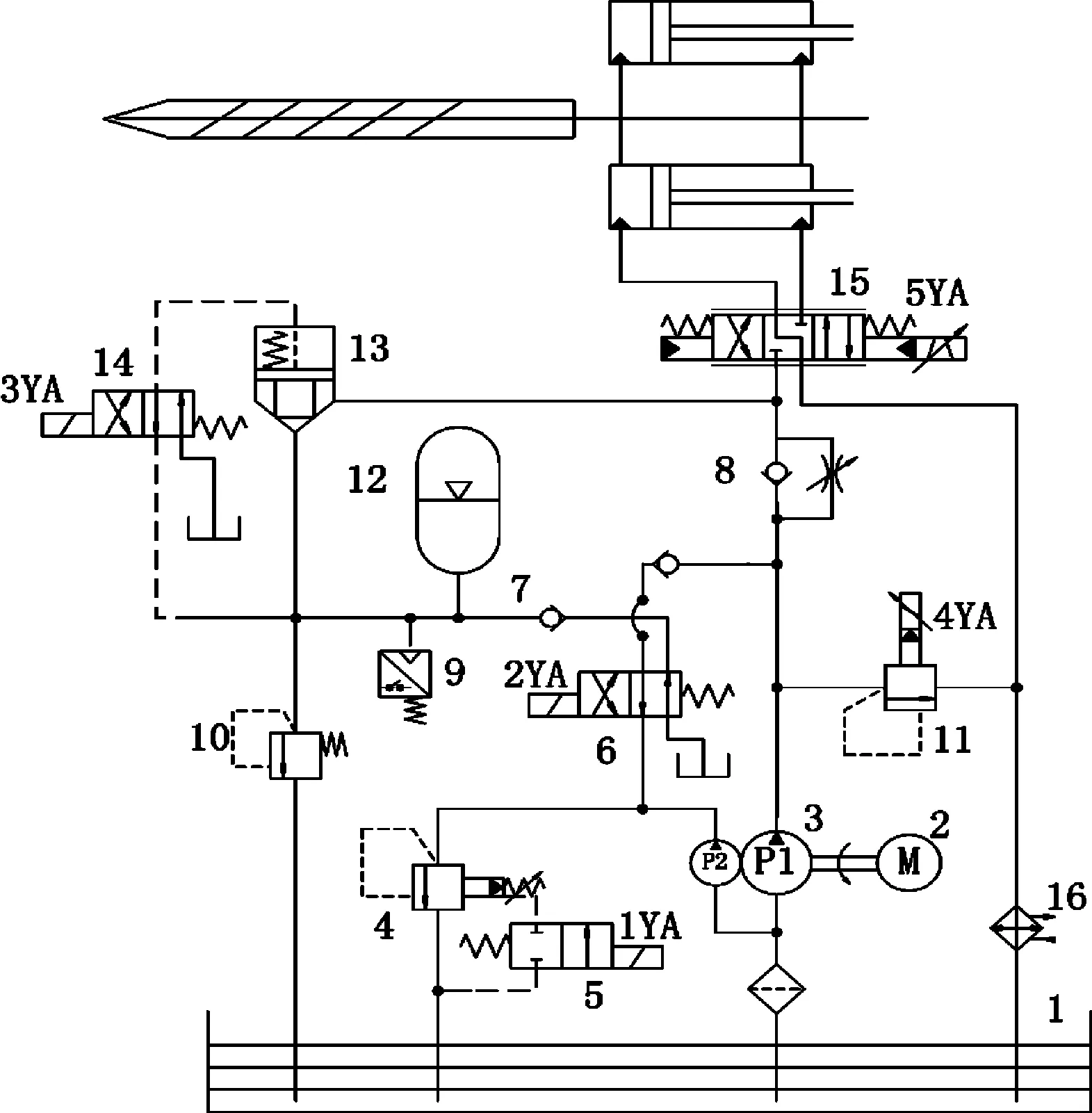
1.tank, 2.motor, 3.double vane pump, 4.relief,5, 6.solenoid directional valve, 7.check valve,8.check-throttling valve, 9.pressure relay, 10.relief, 11.proportional relief valve, 12.accumulator, 13.cartridge valve, 14.solenoid directional valve, 15.servo valve, 16.condenser
Fig.1 The DS160 hydraulic schematic of high-
speed injection system
The working principle of this system is as follows, in non-injection condition, solenoid directional valve 6 is to be energized, the accumulator 12 is filled by high pressure and low mass flow rate pump P2. When pressure reaches the set value of pressure switch 9, the solenoid valve 6 is de-energized and the process of fluid-filled is over. Pump P2 can be unloaded through relief valve 4 or be used to supply oil to system by working with pump P1 through the directional valve 6. When system injects, solenoid directional valve 14 is energized and cartridge valve 13 is opened. Accumulator 12 releases the stored high-pressure oil through servo valve 15 to achieve high-speed injection. The oil flew into injection cylinder can be controlled by controlling the electrical signal to servo valve 15 which determines the opening degree of spool.
2.Components and modeling of hydraulic system
2.1.Servovalve
The functions of servo valves are an electro-hydraulic transfer equipment and also a power amplifier, which is put into a lower electrical signal to get a powerful hydraulic pressure energy and realize the servo control of the screw movement. The servo valve model was taken directly from AMESim hydraulic library (HYD).
System load flowQLand load pressurePLare defined as,
QL=AVL
(1)

(2)
Where,VLis the speed of injection cylinder piston,Ais the piston area of injection cylinder andFLis the load force in injection process.
The servo valve flow rate is usually 1.1~1.3 times greater than the load flowQL, when the supply oil pressure value isPSand the servo valve no-load flow isQNL.
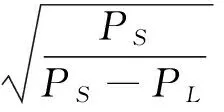
(3)
ConvertQNLto rated flow under the rated pressurePN, then it obtains:
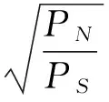
(4)
To combine with MOOG servo valve selection of samples, the determined SV00 simulation parameters are shown in Tab.1.
2.2.Accumulator
The system adopts a bladder accumulator as an auxiliary power source to provide instantaneously high pressure and large flow hydraulic fluid when system injects. HA000 is selected as the accumulator simulation model from HYD and the parameters are as follows: gas pre-charged pressureP0=11.2 MPa, the lowest operating pressureP1=14 MPa, the highest operating pressureP2=17.5 MPa, gas pre-charged volumeV0=40 L, polytropic exponentn=1.4 (isentropic) and the equivalent diameter of drain holed=36 mm.
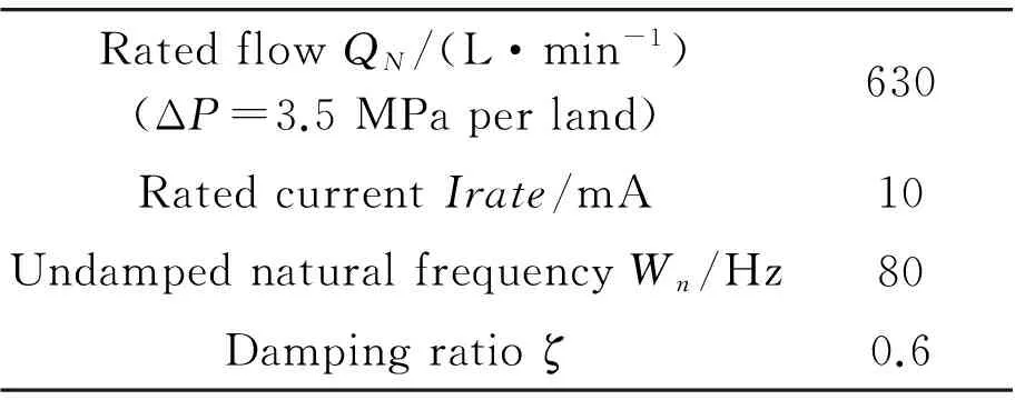
Tab.1 Servo valve simulation parameters
2.3.Cartridgevalve
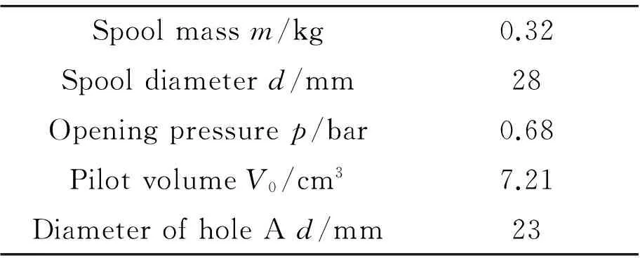
There is no standard cartridge valve model available in AMESim HYD. According to the principles and structure of two-way cartridge valve, a model could be established by using Hydraulic Component Design (HCD) in AMESim software[7-8]. Fig.2 shows a typical structure of two-way cartridge valve, whereAandBare connected to working circuits andCis connected to control circuit. The cartridge valve model built by HCD is shown in Fig.3. The simulation parameters of two-way cartridge valve are shown in Tab.2.
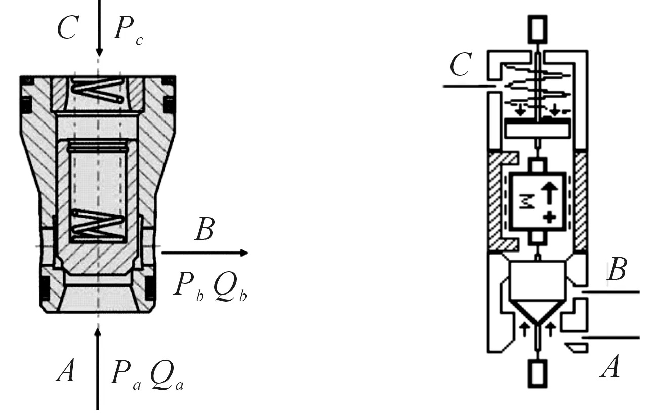
Fig.2 Structure of cartridge valve Fig.3 Cartridge valve model
Spoolmassm/kg0.32Spooldiameterd/mm28Openingpressurep/bar0.68PilotvolumeV0/cm37.21DiameterofholeAd/mm23
2.4.Electro-hydraulicservosystemforinjection
The accuracy of speed and position control of screw during injection process directly affects the quality of molded article. Screw position can be precisely controlled by position servo system. However in the early stage of injection process, the difference between feedback position value and the set value are very large, and the output value of position controller is so big that the opening amount of servo valve is fully opened. Therefore, the injection speed is much greater than the expected value and it can not meet the requirements of injection process. Injection speed could be controlled by adjusting the maximum opening degree of the servo valve spool. However, the injection speed is difficult to be precisely controlled with the increase of discharged oil since the pressure of accumulator decreases during injection process and the resistant force caused by melt plastic filling mold is not a constant. Therefore, the differential pressure of servo valve will be gradually changed and the mass flow rate of oil is not a constant. In this paper, the position-speed servo system control strategy is proposed. In the early stage of injection process, speed servo system will achieve precisely control for the speed of screw; however, when the screw displacement is about to reach the expected value, the position servo system begins to control the screw position precisely. Feedback signals to speed servo system could be obtained by the differential calculation of displacement sensor signal. The control principle is shown in Fig.4.
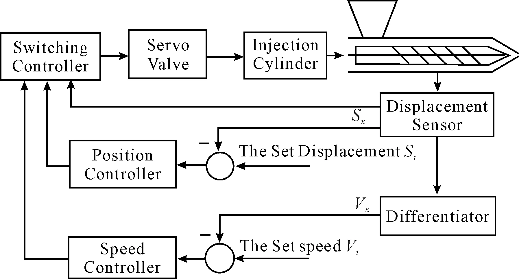
Fig.4 The principle diagram of electro-hydraulic position-speed servo system
2.5.Establishmentofinjectionsystemmodel
In AMESim sketch mode, according to the Fig.1, a complete injection system simulation model could be obtained by using a hydraulic, mechanical and signal library, as shown in Fig.5.
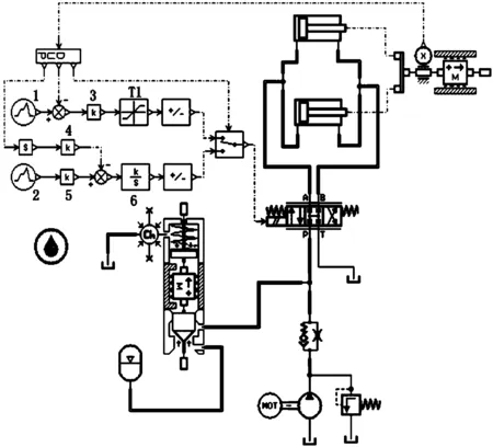
Fig.5 Simulation model of injection system
In order to solve this model, some assumptions are made as follows:
1) Ignore the volumetric efficiency of double vane pump when the load pressure changes and assume it as an ideal quantitative pump.
2) Simplify the load model by using the resistant load model in mechanical library to simulate the complex load force during the melt plastic filling the mold.
3) The injection speed isVI=300 mm/s and the injection displacement isSI=215 mm.
3.Simulation
3.1.Positionservosystemcontrolsimulation
The simulation of position servo system is conducted during injection process under a given position step signal. For different values ofT1:10,9,8,7 to control the maximum opening of servo valve, the screw speed and displacement response curve is obtained as shown in Fig.6 by using AMESim batch function. Fig.6 shows that screw displacement could be precisely controlled to 215 mm and the injection speed could be decreased with the decrease of the maximum opening of servo valve. As shown in Fig.6, the injection speed has poor uniformity and this is caused by the decrease of mass flow rate of oil since the pressure difference of servo valve gets decreased during this process. When T1=9, the pressure difference and flow curves between servo valve inlet port P and outlet port B are shown in Fig.7.
Fig.8 shows the screw speed and displacement response curve for different values of the amplifier gainK3: 500,1 000,1 500,2 000. Analysis shows that ifK3is too small, the position that screw begins to enter position adjustment is far from the expected position along with a longer adjustment time; ifK3is too big, the screw speed at the expected location is prone to oscillate, which causes hydraulic impact and affects system stability.
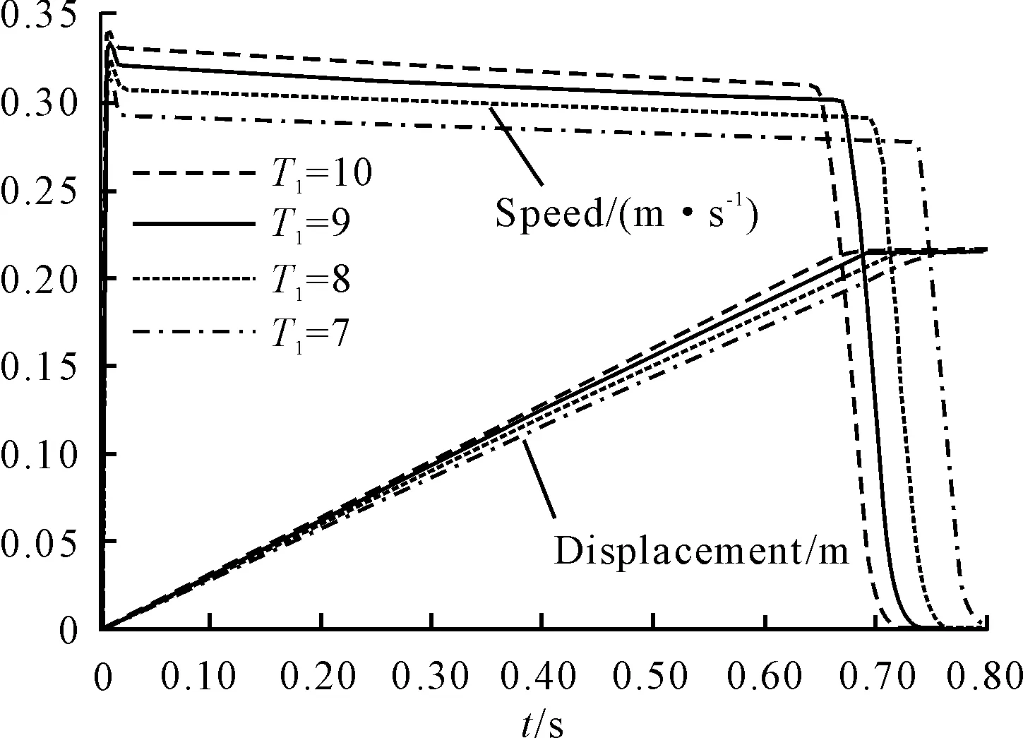
Fig.6 Speed and displacement curve
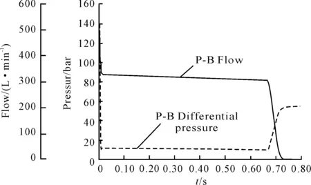
Fig.7 Servo valve differential pressure and flow curve
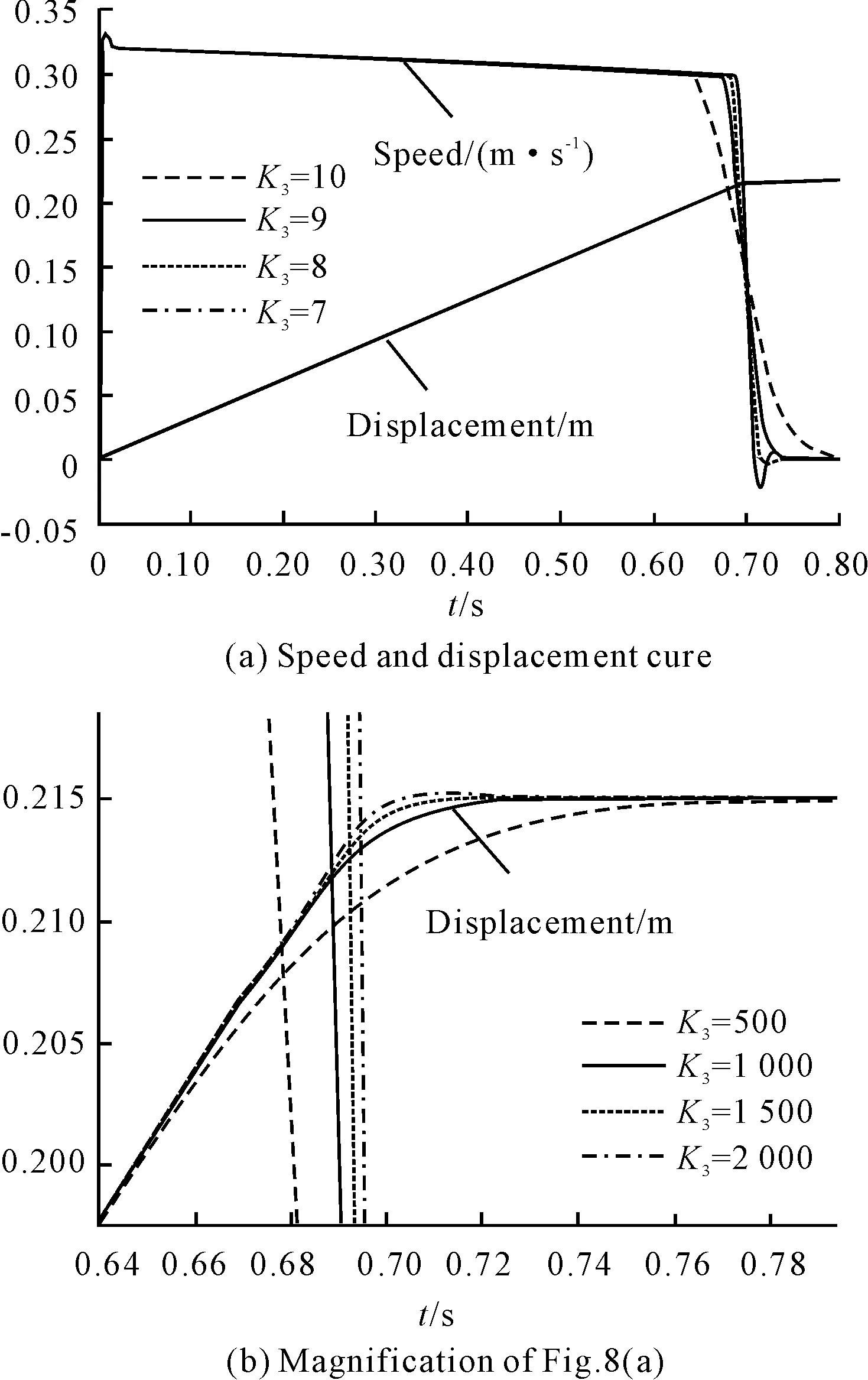
Fig.8 Speed and displacement curve
3.2.Speedservosystemcontrolsimulation
A simulation of speed servo system is conducted during injection process under a given speed step signal. For different values of amplifier gainK6: 300, 600, 2 000, the screw speed response curves are obtained as shown in Fig.9. Fig.9 shows that screw speed could be precisely controlled to 300mm/s and the value of K6 has a great influence on this system. IfK6is too small, system has a slow response and long adjustment time characteristics; ifK6is too big, the system has fast response and big overshoot. Furthermore, the speed is prone to oscillate so that the adjustment time becomes longer and the stability of system declines.
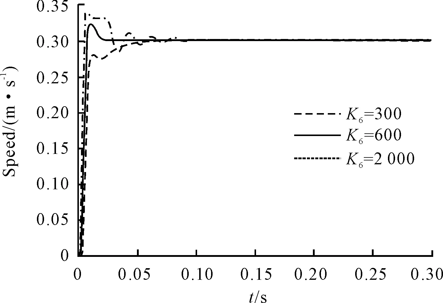
Fig.9 Speed curve
3.3.Position-speedservosystemcontrolsimulation
Position-speed servo system is a compound system of position and speed servo system. The control strategy of this system can achieve that speed control system works in the early stage of injection process and position control system works when the screw position reaches to the expected position. Therefore, the control of speed and position of screw could be achieved at the same time. Fig.4 shows that the switching controller determines the switch between speed and position control, which depends on the comparisons between position sensor feedback displacement signalSXand the setting positionS0.Speed control works whenSX≤S0and position control works whenSX>S0. The difference ΔSbetweenSIandS0is the displacement that the screw starts to enter position control until position error and speed error are both zero. According to Fig.8(b), it could be estimated that ΔS≈0.005 m andS0=SI-ΔS=0.215-0.005=0.21 m which means that when the screw moves 0.21 m, the speed control is switched to the position control via switching controller. As shown in Fig.10, it could be seen that this compound system could achieve a satisfactory control effect during injection process.
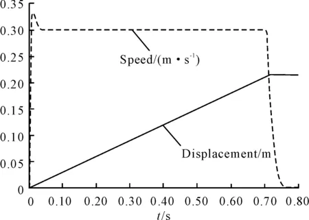
Fig.10 Speed and displacement curve
Fig.11 shows the screw speed and position curve when the switching pointS0is: 0.16 m、0.21 m、0.214 m. When the set value of S0is too small or too big, it will cause the screw speed become unstable and injection displacement becomes so big that it affects the system control precision and stability.
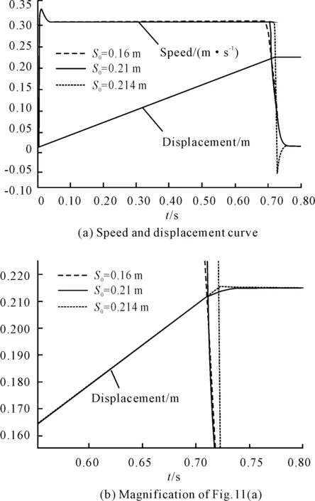
Fig.11 Speed and displacement curve
3.4.Multi-levelspeedinjectionsimulation
Modern injection molding machines could generally achieve at least 3 to 4 multi-speed during injection process. Multi-stage injection requires that screw is at different speed for different stage of injection process. In this paper, a simulation of three-level speed injection is conducted as an example.
Based on position-speed servo system, multi-speed input and multistage gain input of amplifier are applied by the speed controller. In order to simplify the simulation model, the speed controller and position controller by AMESim Super components function are adopted. The packaged speed controller is shown in Fig.12 and the multi-level speed injection simulation model is shown in Fig.13.
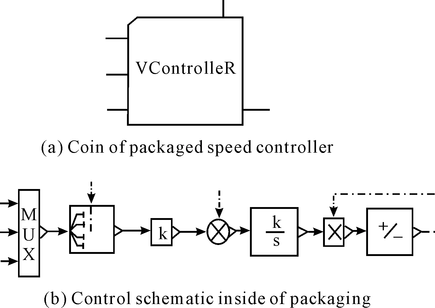
Fig.12 Packaged diagram of speed controller by Supercomponents
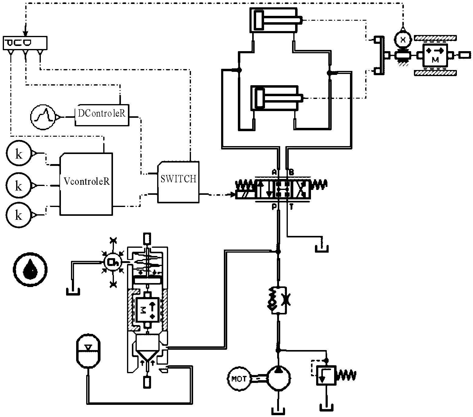
Fig.13 Simulation model of multi-stage injection system
The simulation parameters during multi-stage injection process are as follows: injection displacementSI=215 mm, injection speedV1=150 mm/s,V2=300 mm/s,V3=200 mm/s,speed switching positionS1=20 mm,S2=175 mm. As shown in Fig.14, the screw speed and displacement curve are presented. The simulation results show that position-speed servo system can meet the requirements of multi-level speed injection very well. The screw speed changes at some precise positions and it becomes comparatively stable at 50 ms. Therefore, this system has good response characteristics and stability.
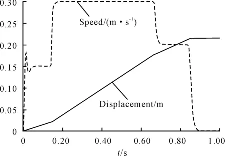
Fig.14 Speed and displacement curve
4.Conclusions
Injection system of injection molding machine has a very high demand on the control of position and injection (actuator) speed. It is very difficult to achieve these both requirements only by position or speed servo system control. The hydraulic system of high-speed injection parts of injection molding machine with position-speed servo system control strategy is proposed and the simulation results show that it is able to fulfill the requirements of the control of screw position and displacement. This strategy also achieves a good simulation results in the complex working conditions such as multi-stage injection process. As mentioned above, the position-speed servo system can fully meet the requirements of high-speed injection system and it could provide a theoretical foundation for the development of high-speed injection molding machine for a hydraulic servo system.
[1] WANG Qiang, WU Zhangyong, LI Hongxing. Simulation Analysis of Electro-Hydraulic Servo Velocity Control System Based on AMESim[J]. Hydraulics Pneumatics & Seals, 2008(4):31-33.
[2] BAI Yanhong, QUAN Long. Control Strategy of the Electro-hydraulic Position and Speed Hybrid Servo System[J]. Journal of Mechanical Engineering, 2010,46(24):150-155.
[3] WANG Chunxing. Hydraulic control system[M]. Beijing: Mechanical Industry Press, 2006.
[4] FU Yongling, QI Haitao. LMS Imagine.Lab AMESim system modeling and simulation-tutorial examples[M]. Beijing: Beihang University Press, 2011.
[5] LIU Laiying. Injection molding process[M]. Beijing: Mechanical Industry Press, 2005.
[6] ZHANG Haijun. Design and Implementation of Injection Molding Machine Hydraulic Servo System[D]. Jinan: Shandong University, 2009.
[7] JIANG Lingling, ZHANG Junjun. Dynamic Characteristics Simulation of Hydraulic Position Servo-system Based on AMESim[J]. Mechanical Engeering & Automatic, 2007(1): 36-37.
[8] WANG Xingtian. Injection technology and equipment[M]. Beijing: Mechanical Industry Press, 2010.
基于AMESim的高速注塑机液压伺服系统的仿真研究
肖 旺,刘军营,刘新钊,胡 鑫,唐敬东
山东理工大学 机械工程学院,山东 淄博 255049
开发了注塑机高速注射部分的液压系统,利用AMESim软件建立了高速注塑机注射系统的仿真模型,分析研究了电液伺服系统中关键参数对螺杆注射过程动态控制效果的影响;提出电液位置-速度伺服系统的控制策略及实现方法,实现了在同一系统中对注射位置、速度双变量的控制,并取得了较好的仿真结果。
高速注塑机;AMESim软件;液压伺服系统
TH137;TQ320
2013-05-19
*XIAO Wang. E-mail: xiaowang_1977@126.com.
10.3969/j.issn.1001-3881.2013.24.016

