双吸平衡式螺杆压缩机整机工作过程的数值模拟一级标题
王小明 ,田青青,贺忠宇,熊国良,罗嗣骁,万长标
1.华东交通大学机电工程学院,南昌 330013;2.沈阳铁路局,沈阳 110000
1.Introduction
Medium septal part[1-2]is the core component of double-suction balance type of screw compressor.Since this part is in the middle of the compressor,it plays an important role to separate the two opposite-arranged working chambers and to form two enclosure compression spaces;meanwhile,medium septal part has special structural design,and works as the joint suction port and the bracing structure of Yin and Yang rotors.
For the sake of mastering the suction system,i.e.,the change of pressure and temperature of medium septal part airflow,numerical simulation of medium septal part is conducted as an effective and simple approach.At first,by using CFD slide meshing technology,the numerical simulation of the whole working process of double-suction balance type screw compressor are obtained[3],the comparative analysis of backflow and eddy situation are performed under different working conditions.Since the simulation results will provide data and example for the optimization design and engineering application,it has important practical application value.
2.Governing equation of fluid motion
At the mercy of physical conservation law,fluid motion must satisfy the continuity equation,momentum conservation equation and energy conservation equation,as shown in Eqs.(1)~(3).
The continuity equation of incompressible fluid could be expressed as Eq.(1):

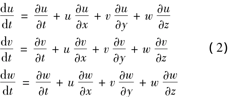
The momentum conservation equation of incompressible fluid without the consideration of fluid viscosity could be expressed as Eq.(2):

The steady state energy conservation equation with a constant heat conductivity coefficient and no internal heat source could be expressed as Eq.(3):

Where,u,v and w stand for the velocity vector of x,y and z direction,respectively.
3.Three-dimensional modeling and meshing
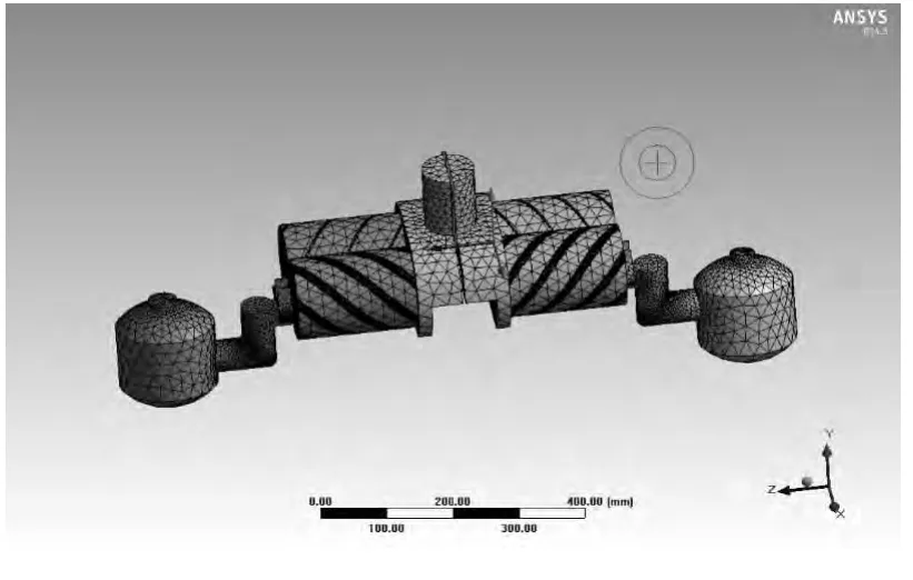
In order to actually simulate the backflow and eddy situation of screw compressor medium septal part,a numerical simulation of the whole system of compressor is necessary.As the complex model of double-suction balance type screw compressor,it is hard to establish the physical model by using ANSYS WORKBENCH.Therefore,PRO/E is used to build the physical model in this paper,and then this model is imported to ANSYS WORKBENCH.Set up interface in the wizard of MESH,and define the meshing type as tetrahedron[4],the minimum mesh size is 2 mm,as shown in Fig.1.The total element number is up to 245076,and pitch point number is up to 1231727.

Fig.1 Meshing of the whole screw compressor
4.Boundary condition
The boundary of inlet and outlet are set as pressure inlet and outlet.The inlet pressure is 0.5 MPa and the outlet pressure is determined by the different condition.The backflow temperature is given.
In this paper,CFD sliding meshing technology is adopted to mesh.Therefore,the Yin and Yang rotors must be set as Solid and the wall is set as moving wall.The rotation origin,rotation axis direction and rotation velocity also need to be given[5-6],and other wall are set as stationary wall.
5.Result analysis
When the outlet pressure is 1.4 MPa,the simulation of the whole double-suction balance type screw compressor is conducted[7].The pressure and temperature distribution of medium septal part are obtained,as shown in Fig.2.From Fig.2,it is clearly presented that the internal pressure and temperature distribution of exhaust seat.

Fig.2 Flow characteristic chart of medium septal part
According to Fig.2(a),the pressure value of medium septal part suction port is only 0.47 MPa.The region with greater pressure distribution is in the medium septal part cavity and the value is about 0.55 MPa.The bulk temperature of medium septal part is not very high,about 270 K,while the highest temperature region is on the both sides,about 320 K.
5.1.Backflow distribution situation under different rotor velocities
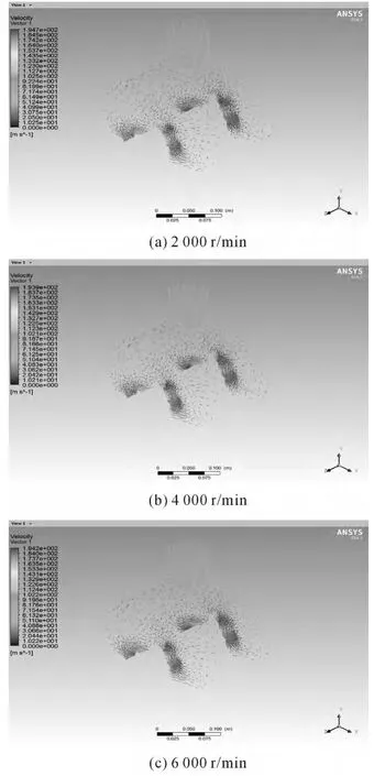
If the exhaust port pressure is kept as a constant,the Yang rotor rotation velocities are 2 000 r/min,4 000 r/min and 6 000 r/min,respectively,the backflow situation will be presented,as shown in Fig.3.

Fig.3 Backflow intensity chart of medium septal part under different rotation velocities
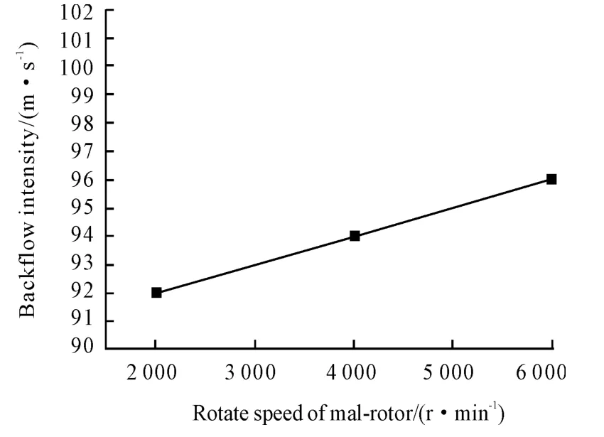
Through comprehensive analysis of backflow intensity under different rotation velocities,the relationships between Yang rotor rotation velocity and medium septal part backflow intensity is obtained,as shown in Fig.4.

Fig.4 Relationship chart between Yang rotor rotation velocity and medium septal part backflow intensity
It is clearly shown in Fig.4 that the backflow intensity is about 92~96 m/s when the pressure is kept as constant,i.e.,the backflow and eddy intensity are almost the constants when the rotor velocity of Yin and Yang rotors are varied in a certain range.
5.2.Backflow distributions under different pressure ratios
When the Yang rotor rotation velocity is kept as constant,the simulation of backflow and eddy intensity of medium septal part is conducted under different pressure ratios[8-9].As shown in Fig.5(a),(b),(c),(d)and(e),the velocity vector distributions are presented when the outlet pressure is 0.8 MPa,1.1 MPa,1.4 MPa,1.7 MPa and 2.1 MPa,respectively.
Through the comparative analysis between the velocity vector distributions of Fig.5,the relationship between pressure ratio and backflow intensity could be obtained,as shown in Fig.6.
It is clearly shown in Fig.6 that the intensity of backflow gets increased with the increase of pressure ratio,which has the same relationship as that of velocity.However,when the pressure ratio is less than 3.5,the change of backflow intensity is not very big;once the pressure ratio is beyond a certain value(i.e.,3.5),the eddy intensity gets increased quickly.When the pressure ratio exceeds a certain value,the software will stop working and,in this situation,there is only backflow but no eddy.

Fig.5 Velocity vector chart of medium septal part of screw compressor

Fig.6 Relationship chart between pressure ratio and backflow intensity
6.Conclusions
Through the numerical simulation of double-suction screw compressor medium septal part,both the internal pressure distribution and temperature distribution are obtained.The relationships among backflow intensity,pressure ratio and Yang rotor rotation velocity are obtained as well.Due to the limited paper space,the influence of screw compress medium septal part structure on the backflow,eddy distribution of suction system is not discussed in this paper.
Reference:
[1] WANG Xiaoming,YANG Zhi,et al.Design of a new twin-screw compressor based on load balanced configuration[J].Machine Tool& Hydraulics,2012,40(11):81-83.
[2] WANG Xiaoming,YANG Zhi,et al.Design of midplate and suction and exhaust ports for a twin-screw compressor based on load balanced configuration[J].Machine Tool&Hydraulics,2012,40(23):96-99.
[3] ZHANG Yuzhu,ZHENG Tao,et al.Analysis and optimization research of welding volute for centrifugal compressors[J].Beijing:China Machine Press,2009(5):82-85.
[4] CHEN Yancheng,GUO Zonghuan,et al.Simulation of Flow Field in the Abrasive Water Jet Nozzle[J].Hydraulics and Pneumatics,2012(10):67-69.
[5] JIANG Fan,CHEN Weiping,et al.Dynamic simulation of flow field inside of lubricate gear pimp[J].Modern Manufacturing Engineering,2007(6):116-118.
[6] HAN Zhanzhong.Fluid simulation calculation example and analysis[M].Beijing:Beijing institute of Technology Press,2009.
[7] LV Yaguo,LIU Zhenxia,et al.Numerical simulation of the two-phase flow in external gear pump[J].Lubrication Engineering,2012,37(1):18-21.
[8] WANG Shuoyuan,GU Bo,et al.The effect of two-exhaust structure on the efficiency of rotary compressor[J].2007,7(3):77-79.
[9] DIAO Anna,XU Mingzhao,et al.Numerical simulation of Gas in Discharge Chanmber of Screw Compressor[J].Fluid Machinery,2009,37(8):29-33.

