Core-Shell Nanospheres(HP-Fe2O3@TiO2)with Hierarchical Porous Structures and Photocatalytic Properties
CHEN Fu-Xiao FAN Wei-Qiang ZHOU Teng-Yun HUANG Wei-Hong,*
(1School of the Environment,Jiangsu University,Zhenjiang 212013,Jiangsu Province,P.R.China;2School of Chemistry and Chemical Engineering,Jiangsu University,Zhenjiang 212013,Jiangsu Province,P.R.China)
1 lntroduction
Recently,considerable interest has been focused on strategy for photodegrading environmental organic pollutants and toxics by solar light.1-4As well known,photocatalytic properties of the catalysts could be significantly improved with modification,and the efforts to manipulate the structure and composition would offer new opportunities to create novel materials with superior photocatalytic performance.So various kinds of catalysts based on different matrixes have been reported,such as metal sulfides,metal oxides,and metal organic complexes.5-7Comparatively,metal oxides possess the natures of adjustable band gaps,nontoxicity,and lowcost,which enables them as good candidates in the field of photovoltaic materials,photocatalysts,and water treatments especially when they have hierarchical structures.8-10
α-Fe2O3,as an important catalyst,has been investigated in-depth for a long time.Moreover,the band gap ofα-Fe2O3is just 2.2 eV,which endows it with responding ability to visible light.However,the poor catalytic activity limits the application ofα-Fe2O3,due to its low electron mobility(generally in the range of 0.01 cm2·V-1·s-4to 0.1 cm2·V-1·s-5),which causes the rapid recombination of electron-hole pairs.11In addition,TiO2has been widely used as a kind of high-efficiency photocatalysts,due to its chemical stability,environmental-friendliness,and higher activity.However,because of its wideband gap energy(Eg=3.2 eV),TiO2can only response to ultraviolet light(less than 387 nm),which makes TiO2take low utilization rate of the solar energy.12Generally,the compatibility of high separation efficiency of photogenerated charge carriers and abundant supply of substrates to the semiconductor surface is a key to achieve efficient photocatalytic reaction systems.Taking into account above reasons,an effective approach to break the limit of above two materials is to establish heterostructure.According to the differences of conduction band potential,the spontaneous migration of photogenerated electrons at the interface results in effective separation of electrons and holes,which improves the quantum efficiency of the photocatalyst.Based on above consideration,corresponding reports have mainly focused on Fe2O3/ZnO,Fe2O3/TiO2,Fe2O3/ZnO/TiO2and others,which show enhanced photocatalytic properties.13-18Therefore,exploring alternative ways to design novel heterogeneous composite materials based onα-Fe2O3may attract more attention in the field of photocatalysis.
Inorganic materials with porous structures have attracted increasing attention due to their large surfaces and favor for the diffusion of solvent,which takes a key effect on the catalytic efficiency.19For example,Xu and Zhu20recently reported the preparation ofα-Fe2O3mesoporous microspheres with hierarchical nanostructure,and the large specific surface areas greatly promote their catalytic activities.Moreover,Ozin group21also found that the macroporous structure could enhance the photodegrading efficiency of TiO2matrix.Min22and Kang23et al.further showed that porousα-Fe2O3architectures exhibited high photocatalytic performance for methyl orange.Inspired by these,we would speculate that combination of the heterogeneous and porous structures in one single sample might endowα-Fe2O3matrix with interesting properties.
Therefore,in this paper,we introduce Fe3O4nanoparticles as the template to design novel materials with core-shell heterogeneous structure.Fe3O4nanoparticles were taken as the core and TiO2gel as the shell.The obtained heterogeneous core-shell spheres were changed into HP-Fe2O3@TiO2through calcination.The micro-structure of samples was characterized by scanning electron microscopy(SEM),transmission electron microscopy(TEM),and high-resolution transmission electron microscopy(HRTEM).Furthermore,the visible and ultraviolet photocatalytic properties of all samples based on different quantities of TiO2have been studied in detail.
2 Experimental
2.1 Materials
FeCl3·6H2O and CH3COONa of analytical reagent(AR)grade were supplied by Sinopharm Chemical Reagent Co.,Ltd.Ti(OC4H9)4(TBT)was purchased from Johnson Matthey Company(U.K.).Ethylene glycol,acetic acid(HAc),and ethanol of AR grade were purchased from Beijing Chemical Corp.All chemical reagents were used as received without further purification.
2.2 Syntheses
2.2.1 Synthesis of Fe3O4spheres
Monodisperse Fe3O4spheres were synthesized by solvothermal reaction according to the literature.242.70 g of FeCl3·6H2O and 7.20 g of CH3COONa were dissolved in 100 mL of ethylene glycol under magnetic stirring.The obtained homogeneous solution was transferred to a Teflon-lined stainless-steel autoclave and heated at 200°C for 5 h.The obtained black magnetite particles were washed with ethanol and deionized water respectively,and then dried in vacuum oven.
2.2.2 Synthesis of Fe3O4@TiO2-gel spheres
0.1 g Fe3O4spheres were dispersed into solution(ethanol:5.75 mL;acetic acid:0.34 mL;TBT:xmL,x=0,1,2,3,4,5),and then the solution was stirred mechanically for 30 min.The magnetic particles were collected by magnets.Finally,the samples were dried in air for 2 days.
2.2.3 Synthesis of HP-Fe2O3@TiO2spheres
The HP-Fe2O3@TiO2spheres were prepared through calcination.Dried Fe3O4@TiO2-gel spheres were put into the crucible and then calcined in a muffle furnace at 450°C for 4 h.The fi-nal samples were yellow-brown.
李老鬼吃着一颗烟,手里的锤子在木船上敲了几下。那艘游艇在这儿晃悠了一圈,见你没来,开到对面的小岛啦,岛上有家大饭店,可能是想请你吃海参鲍鱼什么的。你想见吗?
2.3 Characterization
X-ray diffraction(XRD)patterns were obtained on a D/MAX-2500 X-ray diffractometer(Rigaku,Japan)using CuKαradiation source(λ=0.154056 nm).Specific surface area and pore size were measured by using a NOVA2000e analytical system made by Quantachrome Corporation(USA),the specific surface area was calculated by the Brunauer-Emmett-Teller(BET)method.SEM images were collected on a JSM-6480 field emission SEM(JEOL,Japan).TEM and HRTEM images were collected on an F20S-TWIN electron microscope(Tecnai G2,FEI Co.),using a 200 kV accelerating voltage.A Thermo ESCALAB 250X-rayphotoelectronspectroscope(XPS)equipped with a standard and monochromatic source(AlK hν1486.6 eV)was employed for surface analysis.UV-Vis diffused reflectance spectra of the samples were obtained from a UV-Vis spectrophotometer (UV2550,Shimadzu,Japan),BaSO4was used as a reflectance standard.
2.4 Photocatalytic activity measurement
The photodegradative reaction for methylene blue(MB)was carried out under visible light with a 420 nm cutoff filter and UV light,respectively.The photochemical reactor contained 15 mg samples and 5 mg·L-1of 100 mL MB solution.To determine the initial absorbance of samples,we kept the reactor into darkness for 30 min to reach absorption equilibrium.The photochemical reactor was irradiated with two 150 W tungsten halogen lamps and quartz lamp,which were located with a distance of 8 cm at one side of the containing solution.The sampling analysis was conducted in 10 min interval.The photocatalytic degradation rate(DR)was calculated by the following formula:

where,A0is the initial absorbency of MB that reaches absorption equilibrium,whileAithe absorbency after the sampling analysis.
3 Results and discussion
3.1 Structural characterization
Theproposed mechanism fortheformation ofHPFe2O3@TiO2spheres is described in Scheme 1.

Scheme 1 Proposed mechanism for the formation of HP-Fe2O3@TiO2nanospheres with hierarchical porous structure

Fig.1 XRD patterns of samples
Fe3O4spheres can be easily and largely obtained by the solvothermal method,so we here introduce Fe3O4spheres as templates for designing core-shell HP-Fe2O3@TiO2spheres.After calcination,Fe3O4phase was transferred intoα-Fe2O3phase as observed in Fig.1(a).Compared with Fig.1(h),the calcined product can be attributed to the pureα-Fe2O3(PDF 33-0664),25when the synthesizing process was operated without TBT.Furthermore,a new diffraction peak at ca 30.8°(121),which could be attributed to TiO2(brookite:PDF 29-1360)as shown in Fig.1(g),26,27gradually appeared,which indicated that TiO2phase was formed in the samples.The phenomenon for the formation of just one diffraction peak at ca 30.8°(121)may be due to the two-dimensional structure of the TiO2film coated on the surface ofα-Fe2O3nanospheres,and the following HRTEM image of HP-Fe2O3@TiO2sample further showed uniform(121)crystalline plane of TiO2film,and the similar phenomenon has been also reported by Kuznetsovaet al.28Moreover,the diffraction peak of TiO2was enhanced with the increasing quantity of TBT,while the relative intensity of peaks fromα-Fe2O3became weaker contrarily.Based on above phenomena,it can be indirectly and preliminary proved that TiO2was coated on the surface ofα-Fe2O3.
SEM images of the calcined samples at different synthesizing conditions are shown in Fig.2.Without adding TBT,the sample as pureα-Fe2O3retained spherical morphology very well(Fig.2(a)).The size ofα-Fe2O3spheres is about 200 nm,and theα-Fe2O3spheres maintain a good state of monodisperse.After adding TBT,the obtained HP-Fe2O3@TiO2still exhibited as monodisperse(Fig.2(b-e)),and the size of sphere almost unchanged.However,by increasing the quantity of TBT up to 5 mL,a kind of flocculent gel appeared in Fig.2(f),which could be due to the formation of TiO2gel as the second phase.Therefore,according to the SEM images,we can give the following speculation:when the quantity of TBT is lower than 4 mL during the period of synthesis,the products can keep spherical morphology very well(Fig.2(g)),while the sample became significant adhesion phenomenon with the quantity of TBT up to 5 mL(Fig.2(h)).So,at this condition(TBT:0-4 mL),the TBT should have been attached to the surface ofα-Fe2O3sphere as TiO2shell without forming separate TiO2gel,which further confirms that the core-shell structure is composed ofα-Fe2O3and TiO2.
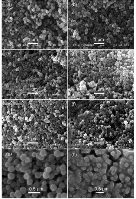
Fig.2 SEM images of samples
Element analysis characterization based on SEM was also measured in order to further study the composition of HP-Fe2O3@TiO2.The sample of HP-Fe2O3@TiO2(4 mL TBT)is taken as an example shown in Fig.3.The energy-dispersive X-ray(EDX)analyzer coupled to the SEM(Fig.3(d))suggests that there are mainly Ti and Fe elements in the samples,and the Fe elements take the dominant part of the samples,which is consistent with the amount of raw materials in the synthesis process.Moreover,in Fig.3(b)and Fig.3(c),the elemental analysis of the resulting nanospheres using secondary electrons by SEM reveals that Ti and Fe elements are uniformly distributed in the samples,which provides another strong evidence for the core-shell wrapped structure of samples.

Fig.3 Element analysis based on SEM images of HP-Fe2O3@TiO2(4 mLTBT)

Fig.4 TEM(a)and HRTEM(b)images of pure α-Fe2O3,TEM(c-e)and HRTEM(f)images of HP-Fe2O3@TiO2(4 mLTBT)
The surface electronic states of the HP-Fe2O3@TiO2(4 mL TBT)sample were further confirmed by XPS analysis.Fig.5 shows the high-resolution Fe 2p,O 1s,and Ti 2pXPS spectra.Fig.5(a)reveals that the Fe 2pXPS spectrum possesses the typical 2p1/2(723.7 eV)and 2p3/2(712.3 eV)peaks fromα-Fe2O3.31In Fig.5(b),the sample exhibits a broader O 1speak(531.7 eV),this broad peak can be corresponded to the O 1sof TiO2andα-Fe2O3.Ti 2pXPS spectrum(Fig.5(c))is identical with Ti 2p1/2and Ti 2p3/2peaks centered at binding energies of 465.4 and 459.8 eV,which are consistent with the typical values for TiO2.32Therefore,the XPS spectra can further reveal that the HP-Fe2O3@TiO2(4 mL TBT)sample is composed of TiO2andα-Fe2O3phases.
3.2 Surface area measurement
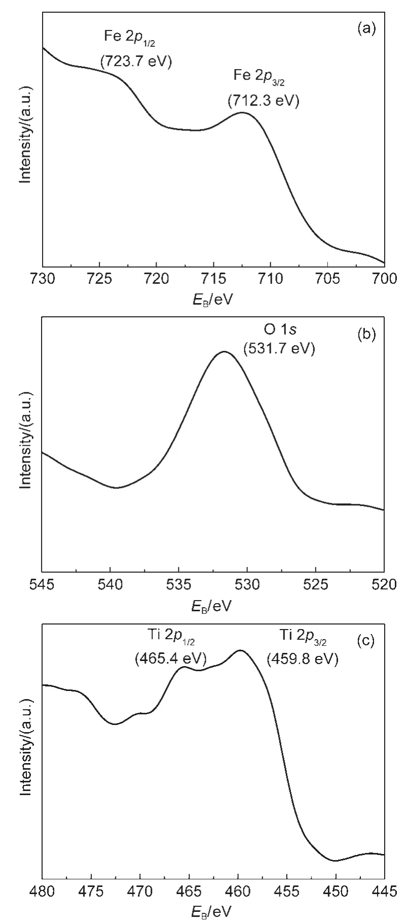
Fig.5 XPS survey of HP-Fe2O3@TiO2(4 mLTBT)
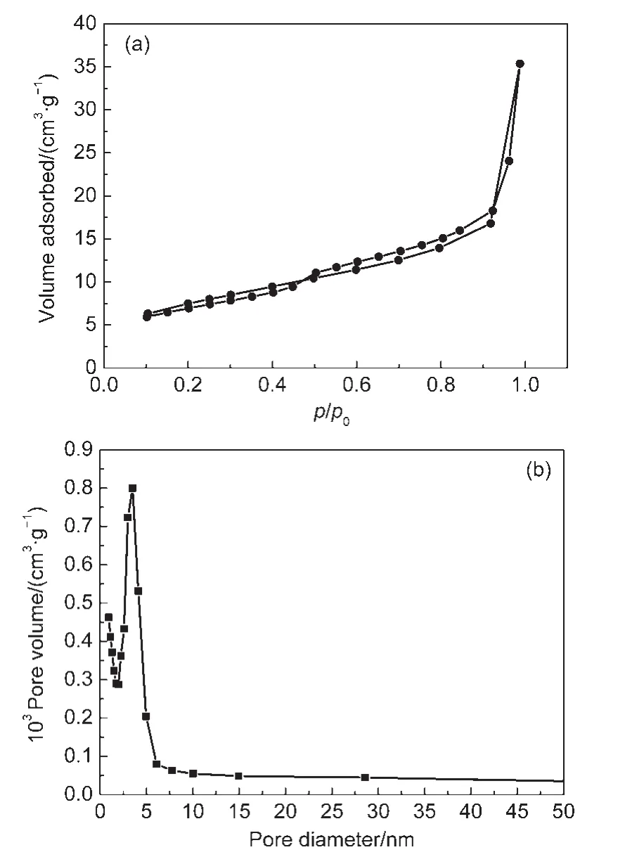
Fig.6 Nitrogen adsorption-desorption isotherms(a)and pore size distribution curve(b)of HP-Fe2O3@TiO2(4 mLTBT)
The porous structure of the HP-Fe2O3@TiO2(4 mL TBT)was further confirmed by nitrogen adsorption-desorption isotherms.As shown in the Fig.6(a),the isotherms are of type IV,33with a hysteresis loop range of 0.5-0.9p/p0(relative pressure).The BET surface area of the sample is 26.5 m2·g-1.The relatively large surface area can be due to hierarchical porous structure composed of macroporous structure and mesoporous structure in samples.Moreover,the pore size distribution curves(Fig.6(b))show that the average diameter of the sample is ca 4 nm,which indicates that the HP-Fe2O3@TiO2(4 mL TBT)sample has been endowed with mesoporous structure.
3.3 UV-Vis absorption spectra
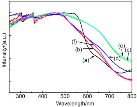
Fig.7 UV-Vis absorption spectra of samples
As shown in the UV-Vis absorption spectra(Fig.7),the samples exhibited broad bands from 600 to 250 nm which belonged to the host absorption ofα-Fe2O3.The band gap ofα-Fe2O3is 2.2 eV(563 nm),which nearly matches with the UV-Vis absorption spectra.34The band gap of TiO2is 3.2 eV(387 nm),so the UV-Vis absorption spectra of HP-Fe2O3@TiO2should give a phenomenon of blue shift theoretically.However,when the TiO2shells were coated on the surface ofα-Fe2O3,the absorption spectra of core-shell HP-Fe2O3@TiO2contrarily extended to 750 nm(red shift)as shown in Fig.7(c)and Fig.7(e),we consider that the phenomenon may be caused by the defect absorption.35,36All the absorption spectra reveal that the obtained samples possess the nature of responding to visible light.
3.4 Catalytic performance
3.4.1 Photocatalytic activity under visible light
Based on the high specific surface area and heterogeneous structure,the photocatalytic activity of the HP-Fe2O3@TiO2has been investigated on degradation of the representative MB organic dye in a solution containing the low concentration of H2O2,where Fenton reagent is effectively formed with H2O2and the generated hydroxyl radical together with holes facilitates the photodegradation of MB.37Fig.8 shows the absorption spectra of MB solution after being irradiated under visible light(λ≥420 nm)for 1 h period.The major absorption(ca 665 nm)in the visible regions decreased with increasing irradiation time,which indicated the significant photodegradation of MB by HP-Fe2O3@TiO2.38Fig.9 shows the photocatalytic degradation ratio and photodegradation kinetics of the MB.All the photodegradations of the MB aqueous solution fit first-order reaction on the whole,which can be expressed as:ln(C/C0)=-kt(kis the apparent first-order reaction constant;C0andCare the initial and the reaction concentrations of MB,respectively).39
In theory,the conduction band ofα-Fe2O3is more negative than TiO2,so the photogenerated electrons can not transfer from the conduction band ofα-Fe2O3to TiO2.However,when the TiO2is formed as the shell on the surface ofα-Fe2O3,theα-Fe2O3/TiO2heterojunction would induce the equilibrium of Fermi levels from TiO2andα-Fe2O3,which makes it possible for immigration from the conduction band ofα-Fe2O3to the conduction band of TiO2.The effective separation of electrons and holes will endow the samples with superiority for suppression of rapid recombination of electron hole pairs,40,41which may be conducive to improving the catalytic activities.However,it is confusing that the catalytic effect reduced with increasing the amount of TiO2(Fig.9),which may be caused by the coverage of TiO2influencing visible light absorption area ofα-Fe2O3in some degree.But,the coverage of TiO2does not affect the contact of internalα-Fe2O3core with the dye solution,because of hierarchical porous structure of the sample.Therefore,a combination of the above two factors would cause the reducing phenomena of the photo-degradation efficiency with increasing the TiO2coverage.Additionally,on the other hand,the catalytic effect is decreased by increasing the amount of TiO2,which provides another evidence for TiO2successfully wrapped on the surface of iron oxide core.
It is obvious that the photocatalytic activity of HPFe2O3@TiO2(1 mL TBT)took the best performance in the visible light,which might be resulted from the following three reasons:(a)the Fe2O3nanospheres coated with TiO2shell can form a heterojunction structure,which could promote the electron-hole separation to improve the photocatalytic activity;(b)the TiO2shell on the surface would shield the absorption of visible light for Fe2O3nanospheres in a certain extent,and this shielding effect becomes significant with increasing the quantity of TiO2shell,which is not conducive to the improvement of the photocatalytic activity;(c)if the amount of TiO2is too much,for example TBT up to 5 mL,the sample would exhibit adhesion phenomenon that remarkably causes agglomeration and reduce dispersibility of Fe2O3nanospheres,which is also not conducive to the enhancement of photocatalytic activity.Therefore,the trade-offs based on the above three parts,the amount of coated TiO2should not be too large.We found that the HP-Fe2O3@TiO2(1 mL TBT)possessed the best performance under visible light,which shows that the surface-coated TiO2can effectively form a heterojunction structure,while the amount of TiO2does not significantly affect the absorption of visible light of Fe2O3nanospheres under this condition.
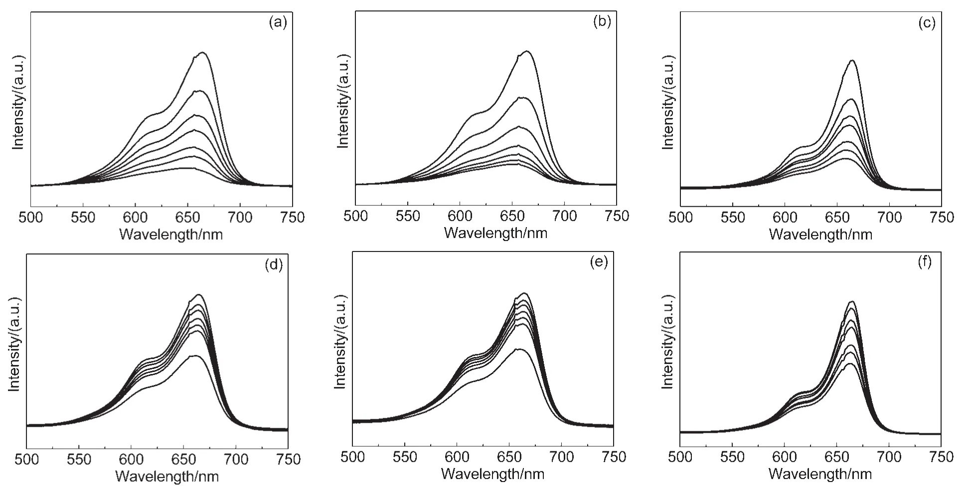
Fig.8 Absorption spectra of MB solution irradiated under visible light
3.4.2 Photocatalytic activity under ultraviolet light
Irradiated by visible light,TiO2,as heterogeneous phase,could effectively separate the photogenerated electrons fromα-Fe2O3.However,TiO2could not produce photoelectron(or hole)under visible light.Therefore,we further studied the photocatalytic properties of the samples under ultraviolet light,sinceα-Fe2O3and TiO2can produce photo-induced electron(or hole)by the ultraviolet excitation,which would greatly improve the photocatalytic effect of the sample.As shown in Fig.10,HP-Fe2O3@TiO2(4 mL TBT)exhibited the best photocatalytic property(Fig.10e),it might be due to the increase of TiO2amount on the surface ofα-Fe2O3which could well respond to ultraviolet light.However,the photocatalytic ratio of HP-Fe2O3@TiO2(Fig.10f)decreased when the amount of TiO2up to 5 mL compared with HP-Fe2O3@TiO2(4 mL TBT),because the excessive TiO2led to the emergence of TiO2gel,which caused the adhesion of the nanospheres and reduction of dispersion,thereby affecting the photocatalytic activity of the sample.42-45
In theory,lights can exciteα-Fe2O3semiconductor to form photoelectron,if the energy is greater than 2.2 eV(wavelengths less than 564 nm).However,due to the certain width of conduction band,photons with large energies may excite photoelectron to the upper edge of the conduction band,these excited state electrons will generally fall to the lower edge of the conduction band through the relaxation process in order to stabilize.During the process of relaxation,some excited state electrons may release their energy in other ways,and eventually return to the ground state of the semiconductor,thereby some excited state electron energy cannot play an effective role in the photocatalytic process.For example,Liet al.46found that:the best photoelectric conversion efficiency ofα-Fe2O3was not in the ultraviolet region,but occurred in the visible light of 400 nm region.Therefore,we consider that this may be one of the reasons for resulting inα-Fe2O3(Fig.10a)with low photocatalytic activity under UV irradiation.

Fig.9 (A)Photocatalytic degradation ratio and(B)photodegradation kinetics of the MB irradiated under visible light
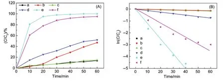
Fig.10 (A)Photocatalytic degradation ratio and(B)photodegradation kinetics of the MB irradiated under ultraviolet light
Furthermore,TiO2can be effectively excited in the ultraviolet lights.Due to the different level structures ofα-Fe2O3and TiO2,it generates heterogeneity structural effects that can effectively enhance electron-hole separation,which may increase the rate of photodegradation.We think that this is the another cause for theα-Fe2O3(under UV irradiation)with lower photocatalytic activity than the HP-Fe2O3@TiO2samples.
4 Conclusions
Core-shell functional nanoparticles with hierarchical porous structure(HP-Fe2O3@TiO2)have been successfully prepared.The obtained HP-Fe2O3@TiO2still exhibited as monodisperse nanospheres,HRTEM further provided insight into the microstructural details,which confirms that the shell is TiO2with both macroporous and mesoporous structure.On the basis of the UV-Vis spectra,the samples possess the nature of responding to visible light.The photocatalysis properties of HPFe2O3@TiO2were studied under visible light and ultraviolet light respectively.Taking into account morphology and photocatalytic property,HP-Fe2O3@TiO2(4 mL TBT)showed the optimal morphology and photocatalytic activity among all the samples under ultraviolet light irradiation.
(1)Zhao,Y.B.;Ma,W.H.;Li,Y.;Ji,H.W.;Chen,C.C.;Zhu,H.Y.;Zhao,J.C.Angew.Chem.Int.Edit.2012,51,3188.doi:10.1002/anie.v51.13
(2)Cong,Y.;Qin,Y.;Li,X.K.;Dong,Z.J.;Yuan,G.M.;Cui,Z.W.Acta Phys.-Chim.Sin.2011,27,1509.[丛 野,秦 云,李轩科,董志军,袁观明,崔正威.物理化学学报,2011,27,1509.]doi:10.3866/PKU.WHXB20110624
(3) Ji,P.L.;Wang,J.G.;Zhu,X.L.;Kong,X.Z.Acta Phys.-Chim.Sin.2012,28,2155.[姬平利,王金刚,朱晓丽,孔祥正.物理化学学报,2012,28,2155.]doi:10.3866/PKU.WHXB201206262
(4)Chen,C.C.;Ma,W.H.;Zhao,J.C.Chem.Soc.Rev.2010,39,4206.doi:10.1039/b921692h
(5) Zhou,Q.;Yuan,B.L.;Xu,D.X.;Fu,M.L.Chin.J.Catal.2012,33,850.[周 强,苑宝玲,许东兴,付明来.催化学报,2012,33,850.]
(6) Zhao,J.C.;Chen,C.C.;Ma,W.H.Topics in Catalysis2005,35,269.doi:10.1007/s11244-005-3834-0
(7)Huang,Y.P.;Ma,W.H.;Li,J.;Cheng,M.M.;Zhao,J.C.;Wan,L.J.;Yu,J.C.J.Phys.Chem.B2003,107,9409.
(8) Tang,J.;Zou,Z.;Ye,J.Angew.Chem.Int.Edit.2004,43,4463.
(9)Xuan,S.H.;Jiang,W.Q.;Gong,X.L.;Hu,Y.;Chen,Z.Y.J.Phys.Chem.C2009,113,553.doi:10.1021/jp8073859
(10) Dotan,H.;Sivula,K.;Grätzel,M.;Rothschild,A.;Warren,S.C.Energ.Environ.Sci.2011,4,958.doi:10.1039/c0ee00570c
(11) Mor,G.K.;Prakasam,H.E.;Varghese,O.K.;Shankar,K.;Grimes,C.A.Nano Lett.2007,7,2356.doi:10.1021/nl0710046
(12)Wang,Q.;Chen,C.C.;Ma,W.H.;Zhu,H.Y.;Zhao,J.C.Chem.-Eur.J.2009,15,4765.doi:10.1002/chem.v15:19
(13)Zhang,H.T.;Wu,X.B.;Wang,Y.M.;Chen,X.Y.;Li,Z.S.;Yua,T.;Ye,J.H.;Zou,Z.G.J.Phys.Chem.Solids2007,68,280.doi:10.1016/j.jpcs.2006.11.007
(14)Liu,Y.;Yu,L.;Hu,Y.;Guo,C.F.;Zhang,F.M.;Wen,X.Nanoscale2012,4,183.doi:10.1039/c1nr11114k
(15)Yang,S.G.;Quan,X.;Li,X.Y.;Liu,Y.;Chen,S.;Chen,G.H.Phys.Chem.Chem.Phys.2004,6,659.
(16)Yan,W.;Fan,H.Q.;Yang,C.Mater.Lett.2011,65,1595.doi:10.1016/j.matlet.2011.03.026
(17)Zhao,H.;Fu,W.Y.;Yang,H.B.;Xu,Y.;Zhao,W.Y.;Zhang,Y.Y.;Chen,H.;Jing,Q.;Qi,X.F.;Cao,J.;Zhou,X.M.;Li,Y.X.Appl.Phys.Lett.2011,257,8778.
(18)Zhu,C.L.;Yu,H.L.;Zhang,Y.;Wang,T.S.;Ouyang,Q.Y.;Qi,L.H.;Chen,Y.J.;Xue,X.Y.ACS Appl.Mater.Inter.2012,4,665.doi:10.1021/am201689x
(19)Zhong,L.S.;Hu,J.S.;Wan,L.J.;Song,W.G.Chem.Commun.2008,No.10,1184.
(20)Xu,J.S.;Zhu,Y.J.CrystEngComm.2012,14,2702.doi:10.1039/c2ce06473a
(21) Chen,J.I.L.;Von Freymann,G.;Choi,S.Y.;Kitaev,V.;Ozin,G.A.Adv.Mater.2006,18,1915.
(22) Min,Y.L.;Zheng,F C.;Zhao,Y.G.;Chen,Y.C.Solid State Sci.2011,13,976.doi:10.1016/j.solidstatesciences.2011.02.005
(23) Cha,H.G.;Kim,S.J.;Lee,K.J.;Jung,M.H.;Kang,Y.S.J.Phys.Chem.C2011,115,19129.doi:10.1021/jp206958g
(24)Deng,Y.H.;Qi,D.W.;Deng,C.H.;Zhang,X.M.;Zhao,D.Y.J.Am.Chem.Soc.2008,130,28.doi:10.1021/ja0777584
(25)Zhu,L.P.;Bing,N.C.;Wang,L.L.;Jin,H.Y.;Liao,G.H.;Wang,L.J.Dalton Transactions2012,41,2959.doi:10.1039/c2dt11822j
(26)Mo,S.D.;Ching,W.Y.Phys.Rev.B1995,51,13023.doi:10.1103/PhysRevB.51.13023
(27) Perego,C.;Wang,Y.H.;Durupthy,O.;Cassaignon,S.;Revel,R.;Jolivet,J.P.ACS Appl.Mater.Inter.2012,4,752.doi:10.1021/am201397n
(28) Kuznetsova,I.N.;Blaskov,V.;Stambolova,I.;Znaidi,L.;Kanaev,A.Mater.Lett.2005,59,3820.doi:10.1016/j.matlet.2005.07.019
(29) Yang,P.;Deng,T.;Zhao,D.;Feng,P.;Pine,D.;Chmelka,B.F.;Whitesides,G.M.;Stucky,G.D.Science1998,282,2244.doi:10.1126/science.282.5397.2244
(30)Yuan,Z.Y.;Su,B.L.J.Mater.Chem.2006,16,663.doi:10.1039/b512304f
(31) Miao,C.H.;Ji,S.L.;Xu,G.P.;Liu,G.D.;Zhang,L.D.;Ye,C.H.ACS Appl.Mater.Inter.2012,4,4428.doi:10.1021/am3011466
(32) Lazarus,M.S.;Sham,T.K.Chem.Phys.Lett.1982,92,670.doi:10.1016/0009-2614(82)83672-5
(33) Kruk,M.;Jaroniec,M.Chem.Mater.2001,13,3169.doi:10.1021/cm0101069
(34)Zhou,X.M.;Yang,H.C.;Wang,C.X.;Mao,X.B.;Wang,Y.S.;Yang,Y.L.;Liu,G.J.Phys.Chem.C2010,114,17051.
(35) Yui,Y.;Ito,S.;Mizuguchi,J.;Ishikawa,Y.;Kiyanagi,R.;Noda,Y.Jpn.J.Appl.Phys.2011,50,013003.doi:10.1143/JJAP.50.013003
(36)Fan,W.Q.;Song,S.Y.;Feng,J.;Lei,Y.Q.;Zheng,G.L.;Zhang,H.J.J.Phys.Chem.C2008,112,19939.doi:10.1021/jp8081062
(37)Zhang,G.Y.;Feng,Y.;Xu,Y.Y.;Gao,D.Z.;Sun,Y.Q.Mater.Res.Bull.2012,47,625.doi:10.1016/j.materresbull.2011.12.032
(38) Pradhan,G.K.;Parida,K.M.ACS Appl.Mater.Inter.2011,3,317.doi:10.1021/am100944b
(39)Tong,G.X.;Guan,J.G.;Xiao,Z.D.;Huang,X.;Guan,Y.J.Nanopart.Res.2010,12,3025.doi:10.1007/s11051-010-9897-2
(40) Peng,L.L.;Xie,T.F.;Lu,Y.C.;Fan,H.M.;Wang,D.J.Phys.Chem.Chem.Phys.2010,12,8033.
(41)Wu,Q.;Ouyang,J.J.;Xie,K.P.;Sun,L.;Wang,M.Y.;Lin,C.J.J.Hazard.Mater.2012,410,199.
(42) Zhu,Y.F.;Piscitelli,F.;Buonocore,G.G.;Lavorgna,M.;Amendola,E.;Ambrosio,L.ACS Appl.Mater.Inter.2012,4,150.doi:10.1021/am201192e
(43) Pan,X.;Zhao,Y.;Liu,S.;Korzeniewski,C.L.;Wang,S.;Fan,Z.Y.ACS Appl.Mater.Inter.2012,4,3944.doi:10.1021/am300772t
(44) Xiong,S.L.;Xi,B.J.;Qian,Y.T.J.Phys.Chem.C2010,114,14029.doi:10.1021/jp1049588
(45)Yang,C.J.;Peng,T.Y.;Deng,K.J.;Zan,L.Progress in Chemistry2011,23,874.[杨昌军,彭天右,邓克俭,昝 菱.化学进展,2011,23,874.]
(46)Ling,Y.C.;Wang,G.M.;Wheeler,D.A.;Zhang,J.Z.;Li,Y.Nano Lett.2011,11,2119.doi:10.1021/nl200708y
- 物理化学学报的其它文章
- Origin of the cis-Effect:a Density Functional Theory Study of Doubly Substituted Ethylenes
- Thermodynamic Properties of Nd(Gly)2Cl3·3H2O and Pr(Ala)3Cl3·3H2O
- Vapor-Liquid Equilibrium Data for Carbon Dioxide+Dimethyl Carbonate Binary System
- lmproving Photocatalytic Performance for Hydrogen Generation over Co-Doped Znln2S4under Visible Light
- 中国化学会第四届全国热分析动力学与热动力学学术会议(第一轮通知)
- 第十一届东方胶化杯全国胶体化学研究生优秀成果奖评选通知

