Nonlinear Parameters Matrix Control and Simulation of Engine Magneto-Rheological Fluids Mounts Isolation System
CHEN Shiwei,LI Rui
1.Academe Math & Phys,Chongqing University of Science. & Technol,Chongqing 401331,China;2.Chongqing University Posts& Telecommunications,Chongqing 400065,China
As a driving force device,vehicle’s engine greatly affect theirs running stability while driving cars,because of the reciprocating motion resulted from the fuel’s combustion.Method of reducing the harm is installing shock mounts(suspension)between the engine and frame,to prevent the engine vibration energy from spreading to the body[1].As one of suspensions,a controllable magneto-rheologicalfluent(MRF)mounts has the advantages oflow energy consumption,equipment is relatively simple,fast response,canrealize the stepless regulationin milliseconds,becomeshot spot inresearchin thefield ofautomotivesemi-active suspension[2].
In the domestic and foreign research on MR suspension applied to semi-active vibration isolation of engine.Lee[3]set the suspension based on MR established 6 degrees of freedom vibration model of engine and applied the LQR optimal control to the vibration isolation of engine,but this control method does not consider the dynamic hardening effect of the suspensions resulted from the high frequency vibration of the engine,and can’t receive great results under the circumstance of wideband and transient state.Rui Li[4]Using MRmountson the engine fortheintelligent fuzzy control,although the intelligent fuzzy controlcanwell solve thevibration system withnonlinear stiffnessproblem,intelligent fuzzy controller needs manual control experience and knowledgeas thecontrol basis and a large number of experimentsto tune the parameters of the controller[5].
Therefore,a fourcylinder fourcycle in line diesel engine adopt in this paper to found a method which feedback system velocity、acceleration and engine speed by an improved instantaneousoptima-algorithm[6-7].The simulation results show the new control method is more effective in different work condition than traditional instantaneousoptima-control.
1.Dynamic model
1.1.Dynamic model of MR mounts
According to Bingham model[8],As shown in Fig.1,when a mounts which manufactured by rubber and MR fluid suffer a displacement excitationx,the reacting forceFeof the mounts can be simplified as stiffness forcek0x,initial damping forcec0˙xand adjustable damping forceFmr.Thence the reacting forceFecan express as:

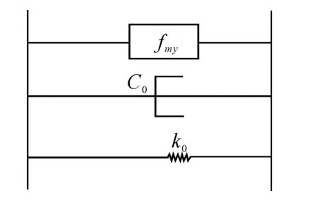
Fig.1 The Bingham Model of MRMount
Dynamic characteristics of a rubber related to the strain rate.Therefore,in Eq.1,kchanges withthe engine rotation frequency.In addition,the adjustable dampingforceFmrdepends the currentIwhich is wired in the mount.Hence,eq.2 gives their relationships by fitting the experimental:

a,b,c,d,eis Fitting constant,is The engine rotationfrequency.
According to Eq.2,the reacting force of the MR mounts can be changed by changing thecurrent,thusachieve active isolation of an engine system.
1.2.The engine mechanical model
For automotive in-line 4 cylinder 4 stroke engine,the establishment of mechanicalmodel as shown in Fig.2:in this model,the powertrain of Engine issited upon a rigid foundationthrough 4MRmount.

Fig.2 Mechanics Model of Engine
Through the establishment coordinatecenter tothe gravity center of the engine,theXaxis is parallel tothe output shaft of the engine,Zaxis perpendicular to thebase plane,Yaxis according to the right-hand rule,so engine can realize Three degrees of freedom(translationalmotion along theZaxis,and the Rotation around theX,theYaxis)of movement in the space.
According tothe mechanics modelandthe existing theory[10],the unbalance forcemain constitute of the direction of theZaxisvertical force,and momentaround theX,Yaxiswhile the engine of this kind working in theignitionway.Eq.3 givesdynamic equation of engine isolation system.

M is Mass matrix.Cis damping matrix,expressed as:

ciis damping of thei-th mounts,xi,yiis coordinates of the join points of mounts,Kis stiffness matrix,expressed as:

kiis stiffness of thei-th mounts,Xis displacement matrix,expressed as:X={z,θ,φ}T,Fiis displacement matrix,expressed as[10]:

Fiis Unbalancedforce.Lis The distance from the center lines of the second or third cylinder to the barycenter.mcis Quality of the Reciprocating parts of piston.ris Radius of the crank.λ is Ratio of the length of the radius of the crank and connecting rod.Mcois Average value of the output torque of the engine.Fris controllable damping force,can be expressed as:

2.The Design of controller
According to the dynamicequations of the system in Eq.3,state equation and output equation of the system are given:


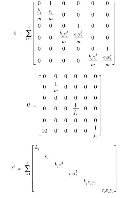
Thinking that each Suspension’smounting points forthehorizontalprojectionisrectangular,getting from the calculation method shown inAppendix,and the input matrix of system has time-dependent nature due to the changes of engine’s rotation frequency,so this paper use the instantaneous optimal control algorithm as shown in Fig.3.Because of the application of instantaneousoptimal feedbackis simple,easy to implement,and the objective function isthe optimal of any time,this algorithm is suitable fornonlinearsystem.Through the improvement of instantaneous optimal control algorithm,the displacement and velocity of the system will be seen as the state variables,and add a feedback of the speed of the engine to conduct the Instantaneous optimal feedback.And then the optimal control considering the nonlinear stiffness of suspension in a wide frequency range of the engine can be achieved.

Fig.3 Schematic diagram of the optimal control system
Differfrom the linear quadratic optimal control,the objective function of the control algorithm is set as the Eq.5,and the physical meaning is:

When the sampling time is sufficiently small,Eq.5can be obtained in accordance with the definition of the derivative:

Substituting Eq.6 into the state Eq.4 can obtain that:

According to Eq.5,Eq.7,Hamilton function is flowing as:

According to the principle of minimum value,the optimal control force vectorUc(t),and the optimal trajectoryX(t)must satisfy the following equation:
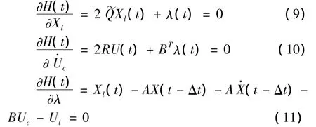
When using the closed-loop control,the optimal control force vector and optimal control is:

In Eq.12,The parameter matrixCis a dynamic feedback matrix related to rotational speed of the engine.As can be seen from this equation,the optimal transmit force at timetis only related to the state of the system on a moment,so the instantaneous obtained by this control algorithm test the rotation speed of the engine at each time stepped to calculate the dynamic feedback formed by matrixC,in order to achieve optimal results of transferring the force to the base in each moment.
3.Simulation Results
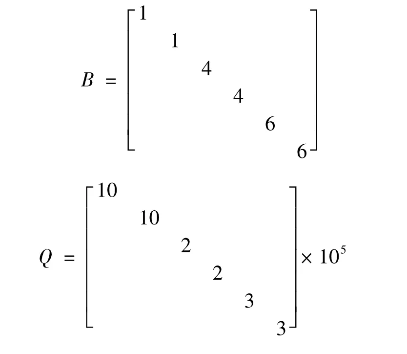
simulation of active control of a 4 cylinder 4 stroke engine vibration obtained from above-mentionedOptimal Control Method,table 1shows the simulation parameters of the system[4,10],consider the MR mounts which has characteristics of low energy consumption and rapid feedback,the isolation system can reduce the transmission that the unbalanced force inZdirection of the engine to the base.Weight matrixR,Q,respectively,positive definite matrix and semi-positive definite matrix.In order to simplify the calculation,the specific values ofRandQin this example respectively is:

Tab.1 Simulation Parameters of The Isolation
3.1.Steady state simulation
Steady state simulation is imitating the active control of the system in case of the rotational speed of the engine is stable.Fig4 is the diagram of the resultant force passed from the cradle to the base when the engine is in the working condition of 1 800 rpm.Fig.5 gives anamplitude diagram of the resultant force passed from the supports to the foundation when the engine are in different working conditions.
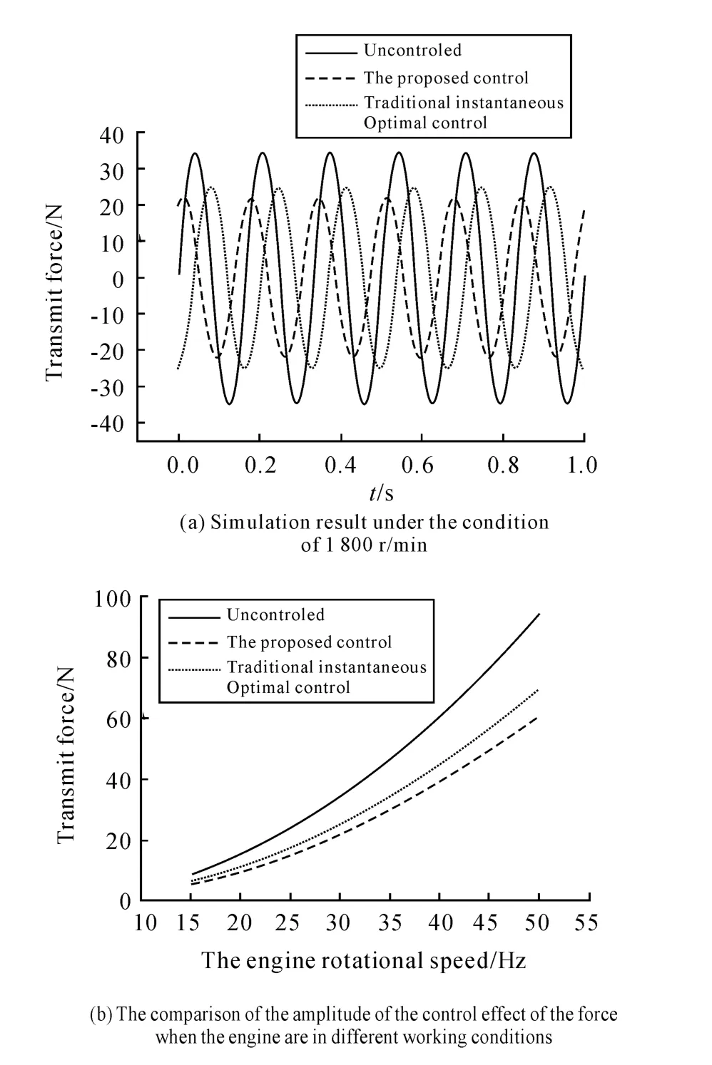
Fig.4 Simulation Result of Steady State
As shown in Fig.5,when the engine rotates at 1 800 rpm stably,compared with passive vibration isolation the Semi-active control of MR mounts can reduce the propagation of the unbalanced force of the engine to the base more effectively.Force amplitude passed from the engine to the foundation is 23.51 N under the control of stiffness nonlinear.Compared with the effect of which taking the stiffness nonlinear instantaneous optimal control into consideration 24.91 N,the isolation effect increased by 5%.However,when the engine speed is increased,the dy-namic hardening increasingly obvious.Compared to traditional instantaneous optimal control method the Improved control method is also more to adapt to the conditions of the engine’s high-frequency.
3.2.Dynamic simulation
Dynamic Simulation is imitating the activecontrol of the system when the speed of the engine is in a rapidly changing.Fig.5a shows the loading path of the engine to simulate the process of change in the rate of rotation of the engine.The process is the engine accelerates following quadratic curve from rest to 3 000 rpm,and then decelerates to 1 800 rpm suddenly after one second,finally,back to the rest from uniform parking.Fig5b,c,d are effect comparison before and after the dynamic simulation of active vibration control,and the active vibration control is given by the above-mentioned method.
Fig.6(b),(c),(d)shows that when the rotational speed of the engine changes rapidly,the results under the control has better stability compared with that under the non-control,and the optimal control of not control system will disappear due to the inertia force of the low-frequency vibration in 3,4 seconds.Comparative Fig.5b,Fig.5(d)can be found when theengine vibratesby thehigh-frequency of 30 Hz compared with the traditional instantaneous optimization the improved methods can reduce 12.8%.
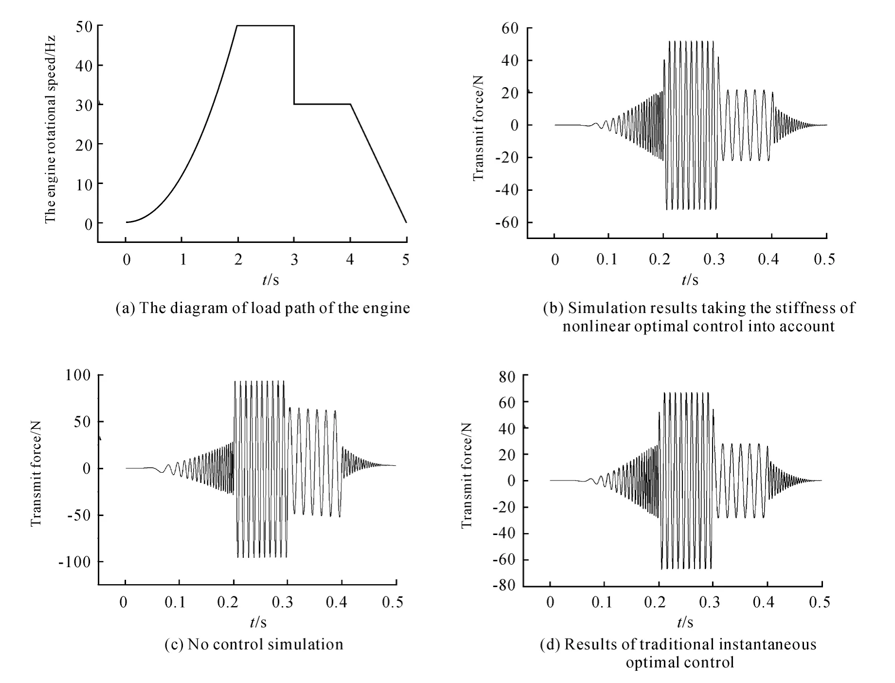
Fig.5 Result of Dynamic Simulation
4.Conclusions
1 Numerical simulation results shows that MR mounts can be applied to the real engine vibration isolationsystem viaimproved instantaneous optimal control.
2 Compared to ordinary instantaneous optimal control,the method which prevent in this paper taking stiffness of nonlinear into account has better isolation effect at the wide band.
[1]Bernard J E,Starkey J M.Engine mount optimization[J].SAE Paper,1983,2:830257.
[2]LIANG Tianye,SHI Wenku,TANG Mingxiang.The summary of study in engine mounting[J].Noise and Vibration Control,2007,27(1):6-10.
[3]Lee D Y,Park Y K.Design and vibration Control of vehicle engine mount activated by MR fluid and piezoelectric actuator[C]//proc.of spie vol.7493 74938T-8.
[4]LI Rui,CHEN Weimin.Fuzzy control and simulation of engine isolation via magnetorhelolgical mountsp[J].Journal of system simulation,2009,21(4):944-947.
[5]DONG Xiaomin.human simulated intelligent control of automobile magnetorheological semi_active suspension[D].Chongqing:Chongqing Universit,2006.
[6]Jann N.New optimal control algorithms for structural control[J].Journal of Engineering Mechanics,1987,9(9),1369-1386.
[7]Jann N.Instantaneous optimal control with acceleration and velocity feedback[J].Engineering Mechanics,1991(6):203-211.
[8]Carlson J D,Jolly M R.MR Fluid Elastomer and Foam Devices[J].Mechatronics ,2000,10(2):555-569.
[9]LIAO Changrong,CHEN Weimin.Issues and their solutions in design of magnetorheological fluid damping devicesp[J].Journal of Functional Materials and Devices,2001,7(4):345-349.
[10]Yan jikuan.Mechanical vibration isolation technology[Z].Publishing house of Shanghai Science and Technology.
[11]PAN xiaoyong.An investigation of calculation methods for the dynamic characteristics of rubber isolator[J].Journal of Vibration Engineering,2009,9(4):344-351.
- 机床与液压的其它文章
- Strength Analysis and Optimization of a Torsion Beam Rear Suspension
- Development of Vibration Signal Acquisition and Analysis System for Machine Tools Based on LabVIEW
- Numerical Analysis and Experimental Research on Micro Milling Process with Cycloidal Tool Path
- Analysis of the Optimization of Gear Pump Pulsation Based on Matlab
- Simulation Evaluation and Performance Analysis of a Double Coil Magnetorheological Valve
- Remote Condition-based Maintenance Approach to Hydraulic System of Construction Machinery

