Selection of Working Parameter for Bladder-type Accumulators with Different Conditions
YANG Yanfang
China University of Mining and Technology ,Yinchuan College,Yinchuan 750011,China
1.Introduction
Accumulator is an indispensable component of modern hydraulic technology.With the development of hydraulic control technology,the accumulator is widely adopted in the industry applications.The most important function of accumulator is to store energy in the hydraulic system and to release the energy when the system is in demand[1].
It is important to develop a software package to design and test an accumulator by using the existing hydraulic system and accumulator theory.Wanqiang Long,who works in shanghai Mayo,developed a smart and convenient software to calculate the volume of accumulator;Par.ker Hannifin Corp designed a calculator called Sharp EL512 to assist the user to select the parameters of different accumulators[2-3].
1.1.The classification of accumulator
Hydraulic accumulators could be classified in terms of the energy carrier and the separating element.
The storage of energy is one of the purposes for the hydraulic accumulators.For the mechanical accumulator,the energy is stored with a type of potential energy.On the other hand,the internal energy of separation medium could be stored for the gas-loaded accumulators.Therefore,the accumulators could be classified by either with or without a separating element[4-5].The hydraulic accumulators with a separating element could be divided into the following types:① bladder-type accumulators,② diaphragmtype accumulators,③ piston-type accumulators.
The principle of these above accumulators is to utilize the good compressibility of gas to store some liquid fluid with worse compressibility.Usually,nitrogen is chosen as the energy carrier.Basically,a hydro-pneumatic accumulator consists of a liquid compartment,a gas compartment,and a gas-tight separating element.The liquid compartment of accumulator is connected to the hydraulic circuit.Therefore,if the pressure of hydraulic circuit gets increased,the gas in the gas compartment will be compressed and the energy could be absorbed by the compressible gas.However,once the pressure of hydraulic circuit gets decreased,the compressed gas could be expanded and the stored energy will be released to push the liquid into the system.
1.2.The function of accumulator
Accumulators have a wide variety of applications in hydraulic systems due to the excellent properties
The main functions of accumulator are as follows:① Energy storage ,② Emergency operation,③Leakage fluid make-up,④Volume compensation,⑤Shock absorption,⑥Pulsation damping ,⑦ Liquid addition.
2.Various factors influence the working parameters
2.1.Influence of poly index
In the charge process of accumulators,the gas index is uncertain.The gas is compressed in the energy absorption process of accumulators.If the compression process is adiabatic,the poly indexn=1.4;If the compression process is isothermal,thenn=1.In fact,the gas compression process of the accumulator is between these two cases.There are two factors which will affect the gas heat transfer.One is the thermal resistance between the gas and the surrounding media and it depends on the accumulator.Another one is the process of experience;it mainly depends on the increase rate of gas pressure.The increase rate of gas pressure will be analyzed as a main factor to affect the poly index.
During the time period Δt,the time-averaged gas compression rate could be evaluated by the ratio of the change of volume and the original volume.Take the limitation of above equation,the compression rate of gas could be obtained as follows[6]:

ΔVsis the absolute change of volume during the time Δt,ΔVuis the volume of liquid fluid entering into the accumulator during the time Δt,VSis the original volume of the gas,Qis the flow of liquid fluid entering into the accumulator.
Ifn=f(ε),the charging process is isothermal:
The charging process is adiabatic:
For bladder accumulator,the formula is as follows:


2.2.Influence of the temperature
In the operation cycle,the temperature of system could be changed.Since the volume of liquid/gas is the function of temperature,the influence of temperature should be taken into account.Due to the relationship between temperature and pressure and the Lussac Law,the relationship between pressure and volume could be obtained.When the temperature of system decreases,the pressure of the charge process will be decreased,and the storage capacity of accumulator will decrease as well.
Therefore,in order to accumulate to ΔV,greaterV0is indispensably required.The relationship between the pressure and the volume is as follows:

T1=θ1(℃)+273=the minimal temperature(K),T2=θ2(℃)+273=the maximal temperature(K),V0is the calculation volume without temperature change(L),V0Tis the increased volume with change of temperature(L).
2.3.The total volume formula of the accumulator
The total volume of the accumulator could be obtained as follows:

P0is charging pressure of the gas space with the fluid space depressurized,P1is minimum pressure required to open the valve,P2is maximum operating pressure of the hydraulic system with bladder and diaphragm accumulators,ΔVis Effective volume.
3.Programming and implementation of accumulator selection and accumulator working parameters calculation
3.1.Flowchart of the software
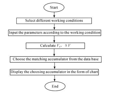
Accumulator calculation and accumulator working parameters selection are very important part of the software package[7-10].The calculation flowchart is Fig.1.
3.2.Calculating program of the total volume
Based on the poly index formula(3)and the accumulator total volume formula(5),the accurate total volume and the poly index of accumulator for the volumeV0 could be obtained.The Visual Basic language was adopted to program the main interface.The corresponding functional modules were compiled according to the different requirements and the Access was used as database to collect all the data of accumulator.Based on this software package,once user confirmed all the input parameters,an appropriate accumulator could be obtained.The final result will be presented in the form of chart.
The code of programing is as follows:

3.3.Examples of Application
When the accumulator is used for volume compensation,if a pipe with internal diameterd=77.7 mm and the lengthL=120 m,the oil inside the pipe flows under the pressure of 10 bar;θ1=10℃,θ2=45℃;the change range of pressure is ±8%and the working temperature is between 25℃ and 70℃.
1)Effective volume formula is defined as follows:

VTis the volume of pipeline(L),θ2is the maximum temperature of system(℃),θ1is the minimum temperature of system(℃),β is fluid coefficient of cubical expansion,Kbis fluid coefficient of linear expansion of pipelines.
2)The value of each parameter:

Fig.1 The flowchart of selection and calculation of Accumulator

3.4.Application of the software
1)Interface is Fig.2.

Fig.2 The initial interface of the software
2)Select working conditions interface is Fig.3.

Fig.3 The interface of selecting working condition
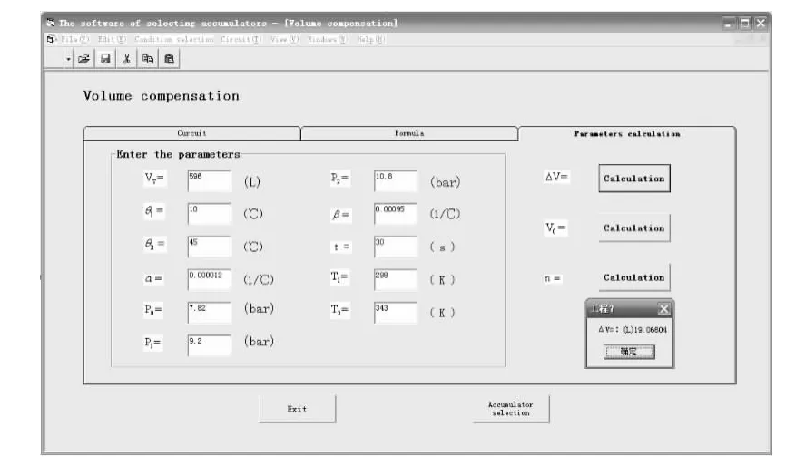
3)Calculate the effective volume value ΔVis Fig.4.
Press the“Calculation”button,then a message box displays ΔV=19.066 04 L.

Fig.4 The interface of calculating the useful volume
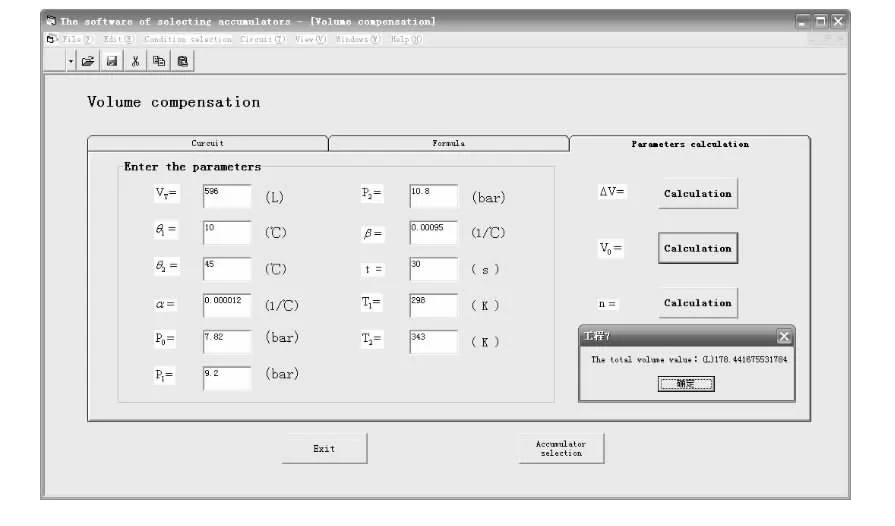
4)Calculate the total volume valueV0is Fig.5.

Fig.5 The interface of calculating the total volume
Press the“Calculation”button,then a message box displaysV0=178.44 L.
5)Calculate the poly index at the condition ofV0 is Fig.6.

Fig.6 The interface of calculating the poly index of accumulator for the volume V0
Press the“Calculation”button,then a msgbox displaysn=1.035 744.
6)Use the Access to establish the accumulator database,and chose the matching accumulator according to theV0andP0is Fig.7[2].
7)The detailed information of the accumulator selected is Fig.8.

Fig.7 The interface of the matching accumulators from database

Fig.8 The interface of the detailed information of the accumulator selected
4.Conclusions
In this paper,a software package for accumulator was developed,and this software can provide precise total volume value.According to the total volume value,the database will recommend a proper accumulator.The software has friendly user interface and it is easy to use and understand.
The accumulator software package still needs further improvement.After the calculation of total volume and recommendation of matching accumulator,this software suppose to call the Simulink in Matlab to build dynamic model of hydraulic loop to dynamic analysis.And another function of this software should be improved to check whether the accumulators meets the requirements or not.It provides an accurate basis for hydraulic system to choose appropriate accumulator and made full use of accumulator.
[1]KONG Xiangdong,QUAN Lingxiao.The History,Current Situation of Accumulator’s Research and its Vista[J].MACHINE & HYDRAULICS,J2004(6):105..
[2]Chamberlain J,Flippo W.Making the choice-bladder or piston accumulator[J].HYDRAULICS & PNEUMATICS,1987(11):58-64.
[3]Flippo W T.Sharp EL512 Calculat or Helps Size Accumulators[J].HYDRAULICS &PNEUMATICS,1985(6):106-109.
[4]MA Yali,HUANG Zhijian.Accumulator practical techniques[M].Beijing:Chemical industry press,2007.
[5]ZHOU Entao.The manual of designing and selecting the hydraulic system components[J].Beijing :China Machine Press,2007:740-753.
[6]WANG Dewei.Determination of the Gas Poly tropic exponent in the Charge Process of the Energy Accumulator[J].HYDRAULICS & PNEUMATICS,2007(9):106.
[7]ZHAO Qi.The computer aided design of accumulator and working loop[D].Qinghuangdao:Yanshan University,2001.
[8]LI xi,ZHANG Cong,CHAI Xin.Visual Basic Programming fundamentals[M].Beijing:China Railway Publishing House,2005.
[9]WANG Jiasong.Visual Basic development experts[M].Beijing:Publishing house of electronics industry,2008.
[10]LI Minye,WANG Ying.The complete analysis of Visual Basic & Access database applications[M].Beijing:Posts& Telecom Press,2004.
- 机床与液压的其它文章
- Strength Analysis and Optimization of a Torsion Beam Rear Suspension
- Development of Vibration Signal Acquisition and Analysis System for Machine Tools Based on LabVIEW
- Numerical Analysis and Experimental Research on Micro Milling Process with Cycloidal Tool Path
- Analysis of the Optimization of Gear Pump Pulsation Based on Matlab
- Simulation Evaluation and Performance Analysis of a Double Coil Magnetorheological Valve
- Remote Condition-based Maintenance Approach to Hydraulic System of Construction Machinery

