Data Center Network Architecture
Yantao Sun,Jing Cheng,Konggui Shi,and Qiang Liu
(School of Computer and Information Technology,Beijing Jiaotong University,Beijing100044,China)
Abstract The rapid development of cloud computing has created significant challenges in data center architecture.In this paper,we discuss these challenges.We introduce the latest research on data center network architecture,especially in terms of structure and virtual machine migration.We also introduce research in areas related to network architecture.Finally,we suggest futureresearch areasin datacenter networks.
Keyw ords data center network;network architecture;network topology;virtual machinemigration
1 Introduction
T he history of data centers can be traced back to the 1960s.Early data centers were deployed on mainframes that were time-shared by users via remote terminals.The boom in data centers came during the internet era.Many companies started building large internet-connected facilities,and these were called internet data centers(IDCs)[1].In 2006,Google first proposed cloud computing;and later,Amazon,Microsoft,Yahoo,IBM,and other IT companies put great effort into promoting it.Cloud computing requires data center networks(DCNs)to be scalable,flexible,powerful,and energy-efficient.
A large-scale network and virtual machine(VM)migration are the main features of today's data centers,and cloud computing is the most important service in data centers.There are many problems in data centers that researchers have been trying to solve.Research on DCNs has become very important in the field of computer networks.Every year since 2008,SIGCOMM and INFOCOM have both included special sessions to discuss research on data DCNs.
Some papers have been written on the problems of current data centers. In 2009, Krishna Kant introduced state-of-the-art DCN technologies and discussed storage,networking,management,power,and cooling in data centers[2].In thesame year,Albert Greenberg et al.described costsin data centers and methods to reduce these costs[3].In particular,they pointed out that conventional network architecture lacks agility,and they discussed principles that should be followed todesign an agilenew architecture.
Especially after 2008,DCN technologies have developed rapidly,and much innovative research has been done on network architecture and protocols,QoS,VM migration,and configuration and management.Kant and Greenberg's works do not cover thelatest research.
In thispaper,weintroducethelatest research on DCNarchitecture,including research on network structure and VM migration solutions.In section 2,we discuss existing problems in current DCNs.In section 3,we compare network architectures proposed in recent years.In section 4,we review the latest solutions for migrating VMs over the entire data center.In section 5,we introduceresearch related to DCNarchitecture.Section 6 concludesthepaper.
2 Issuesin Existing DCNs
A multiroot tree structure is commonly used in today's data centers.In such a structure,many layer-2 domains are connected via layer-3 networks.Fig.1 shows a conventional DCN architecture[4],[5].Many server nodes connected via switches constitute a layer-2 domain.In practice,a single layer-2 domain is limited in size to about 4000 servers because of the need for rapid convergence when there is a failure.Furthermore,a layer-2 domain is divided into subnets by using virtual local area networks(VLANs).Each VLAN has no more than a few hundred servers,because the overhead of the broadcast traffic,for example,address resolution protocol,limits the size of an IPsubnet.
There are two salient problems that prevent conventional architecture from supporting a large-scale data center with up to tensof thousandsof serversat onesite.
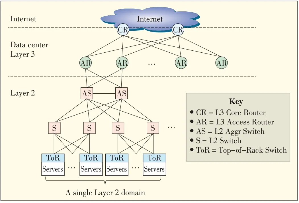
▲Figure1.Conventional DCNarchitecture.
The first of these problems is a shortage of bandwidth in the higher layers.In practice,the typical oversubscription ratio between neighboring layers is 1:5 or more.In the top layer,this ratio may reach 1:80 to 1:240.Even if the fastest,most advanced switches and routers are used,only 50%of the aggregation bandwidth of edge networks can be supported in the top layer[3].The top layer is therefore becoming the bottleneck of theentirenetwork,especially in today'scloud computing environment where the requirement for intra-network traffic is increasingrapidly.
The second problem is that VM migration is limited in a single layer-2 domain;that is,a VM cannot move from one layer-2 domain to others.VM migration is a very important feature of cloud computing data centers.By leveraging VM migration,a data center can save energy[6],[7],improve scalability and reliability[8],and rapidly deploy services[9].In conventional networks,different layer-2 domains have different IP ranges,so a VM has to change its IPaddress when it migrates to other layer-2 domains.In many applications,service cannot be interrupted during VM migration,and this requires the VM's IPaddress to remain unchanged,even when the VMmigrates to another domain.This is an urgent dilemma that has to be solved in new data center architectures.
With the rapid development of cloud computing,the demand for large,centralized data centers has become urgent worldwide.New network architectures are required because existingarchitecturesdon't work well.Therearemany other issues related to DCNs,including QoS,routing protocols,and network configuration,but we do not broach themin this paper.
3 Network Structure
To solve bandwidth and scalability problems,researchers have proposed many novel DCN structures over the past several years.These structures can support up to tens of thousands of servers without any bandwidth bottleneck.Generally,these network structures can be categorized as switch-centric,server-centric,or irregular.In a switch-centric network,switches are the fundamental components of the network fabric;servers are attached to access switches and are the leaves of network.In a server-centric network,servers provide both computing and routing and are the main network components.Unlike irregular networks,switch-centric networks and server-centric networks both have regular,symmetrical topology.An irregular network hasan arbitrary topology.
3.1 Switch-Centric Networks
In 2010,a fat-tree network was proposed at SIGCOMM[10](Fig.2).A fat-tree network is divided into core layer,aggregation layer,and edge layer,and all the servers are connected to the switches in the edge layer.A fat-tree network is a multipath network in which there are many equal-cost paths between adjacent layers.It is also non-blocking and can have an oversubscription ratio of up to 1:1.Therefore,it eliminates the bandwidth bottleneck in the core layer.Furthermore,a fat-tree topology can support large-scale networks with tens of thousands of physical servers.Using 48-port switches,it can contain up to 27,648 servers with 2280 switches.Because a fat-tree network can be constructed using cheap Ethernet switches,it costs less than a conventional network.To leverage the vast bandwidth of multiple paths,a novel routing method is used in afat-treenetwork.
To support non-blocking communication,the fat-tree architecture requires a large number of switches in the core and aggregation layers as well as wires interconnecting these switches.These make the fat-tree network very expensive,energy intensive,and complicated to manage.In VL2[11],Helios[12],and c-Through[13]topologies,cheap core and aggregation switchesarereplaced with expensive,high-speed switches.
VL2 was proposed by Microsoft in 2009.In VL2,a Clos network is used to build the DCN(Fig.3).Other than 1 Gbit/s switches in fat-tree,VL2 leverages 10 Gbit/s switches in the core and aggregation layers,so the link speed between core and aggregation layers is 10 times faster than in fat-tree.Also,the number of links required between the core and aggregation layers is only 10%that required in the fat-tree.One weakness of VL2 is that the maximum supported network size is only half that supported by fat-tree.
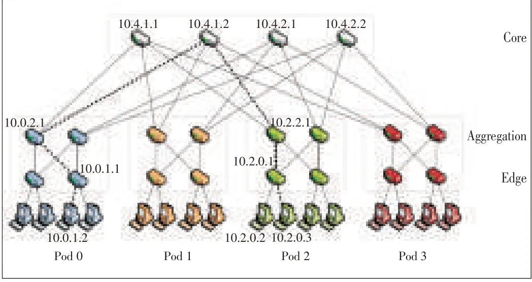
▲Figure2.Fat-treenetwork topology.
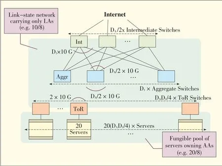
▲Figure3.VL2 topology.
Helios is a hybrid electrical/optical switch architecture[12](Fig.4).In Helios,core switches are replaced with optical circuit switches,and copper cables are replaced with optical fibers to connect the pod switches to core switches.Circuit switches are used to deliver baseline,slowly changing inter-pod communication.Packet switches are used to deliver bursty inter-pod communication.Another hybrid electrical/optical DCN is called c-Through[13].In c-Through,the entire network comprises an electrical packet-switched network and an optical circuit-switched network.The packet-switched network uses a traditional hierarchy of Ethernet switches arranged in a tree,and the circuit-switched network connects the top-of-rack switches.The optical circuit switch automatically reconfigures circuits between top-of-rack switches to achieve themaximumthroughput.Tomakethebest useof high-capacity circuits,servers buffer traffic in order to collect sufficient volumesfor high-speed transmission.

▲Figure4.Heliostopology.
The several previously-mentioned architectures are all based on the multi-root tree structure.Conversely,HyScale[14]is a non-tree structure that has high scalability and that uses hybrid optical networks(Fig.5).It uses optical burst switching for transmitting low volumes of data and optical circuit switching for transmitting high volumes of data in a data center.HyScale is a recursively defined topology denotedΨ(k,Φ,T),where k is the number of levels in the topology,T is an integer,andΦis the address space of all nodes inΨ[14].A HyScale is constructed by connecting T of k-1 HyScales,that is,Ψ(k-1,Φ,T)[14].
In 2011,we proposed MatrixDCN,another non-tree structure[15].In MatrixDCN,a switch may be a row switch,a column switch,or an access switch.Access switches are deployed as a matrix with rows and columns.An 8×8 matrix has 8 rows,8 columns,and 64 access switches.A row switch is deployed at the head of one row and links all the access switches in the row.A column switch it is deployed at the head of a column and links all the access switches in the column.Fig.6 shows a 2×2 MatrixDCN.With 48-port switches,MatrixDCN can support up to 100,000 servers without bandwidth bottleneck.This fabric is simple and extendable,and its routing is very effective.Furthermore,the fabric supports one-to-many and many-to-many traffic in cloud computing.
3.2 Server-Centric Architectures
DCell is a recursively defined architecture that uses servers with multiple network ports(Fig.7)[16].A high-level DCell is constructed from low-level DCells,and low-level DCells are connected together via links between servers.A DCell can scale exponentially with the server node degree.Therefore,a DCell with a small server node degree can support up to several million servers.However,DCell has a low bisection bandwidth that may lead totraffic jamin thenetwork.
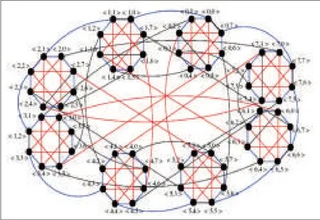
▲Figure5.HyScale Topolgy[14].
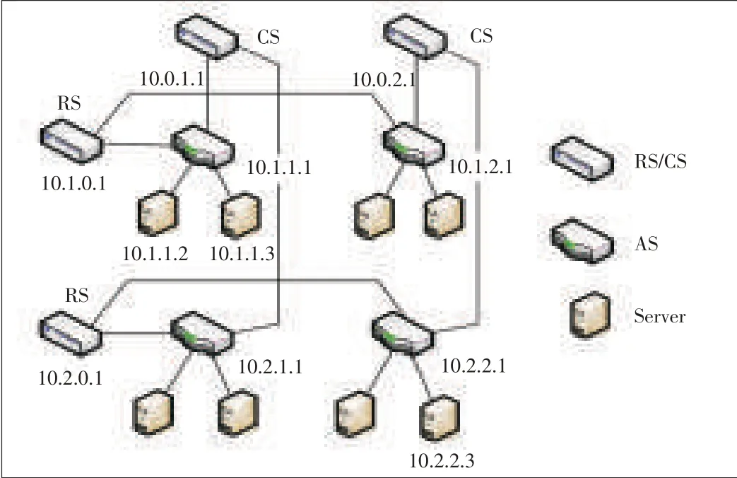
▲Figure6.MatrixDCNtopology.
FiConn shares the same design principle with DCell.The network is constructed by giving the interconnection ability to servers[17].Unlike in a DCell,the server node degree in a k-level DCell is k+1;however,that of FiConn is always two.Today's commodity servers usually have two Ethernet ports—one for network connection and one for backup.FiConn only uses the existing backup port for interconnection;no other hardware cost needs to be incurred by adding to the servers.
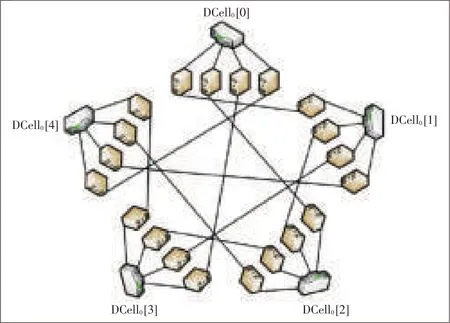
▲Figure7.DCell topology.
BCube provides more bandwidth in the top layer than DCell[18](Fig.8).BCube comprises multiport servers and switches that only connect with servers.A BCubekhas N=nk+1servers and k+1 levels of switches.Each level has nkn-port switches.BCube can also support very large networks.With 3-port servers and 48-port switches,a data center can be constructed that containsmorethan 100,000 servers.
DPillar comprises n-port switches and dual-port servers[19](Fig.9).The servers are arranged into k columns and so are the switches.Visually,the topology looks like the 2k columns of servers and switches that are attached to the cylindrical surface of a pillar.A server in each server column is connected totwoswitchesin thetwoneighboringswitch columns.
An expansible DCN structure using hierarchical compound graphs has also been proposed[20].The structure is called bi-dimensional compound network(BCN),and compared with the previously mentioned structures,it is more complicated.Like DCell,it does not eliminate traffic bottleneck.
3.3 Irregular Networks
Most DCN architectures have a regular symmetric topology.However,an asymmetric data center topology called Scafida has been proposed[21].It is inspired by the scale-free Barabási and Albert topologies[21].In Scafida,the network structure is generated iteratively according an algorithm.The nodes are added one by one to the network.A new node is attached probabilistically to an existing node proportional to the existing node's degree.New nodes have more than one link,so they are attached to several existing nodes.In Scafida,a node'sdegree(links)is limited to the number of itsports.
Existing solutions to data center scalability require the network architecture to be changed.However,a scheme called traffic-aware virtual machine placement has been proposed to improve network scalability[8].It works by optimizing the placement of virtual machines without changing the network structure.
REWIRE is a framework for designing,upgrading,and expanding DCNs[22].In REWIRE,unstructured networks are built instead of topology-constrained networks,which are found in most existing data centers.It uses local search to find a network that maximizes bisection bandwidth while minimizing latency and satisfying a large number of user-defined constraints.Demonstrations have shown that arbitrary topologies can boost DCN performance and reduce expenditure on network equipment.
3.4 Other Structures
Containerizing is an important trend in data centers.In 2007,Microsoft proposed using standard shipping container to modularize data centers[23].A data center module comprising more than 1000 pieces of equipment can be built in a shipping container with full networking support and cooling.Each module includes networking gear,compute nodes,and persistent storage.The modules are self-contained with enough redundancy so that individual failed systems do not need to be replaced.A large data center container is packed with 1k to approximately 4k servers.
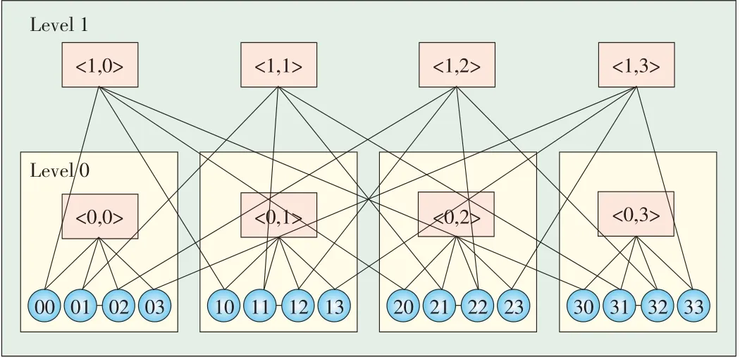
▲Figure8.BCubetopology.
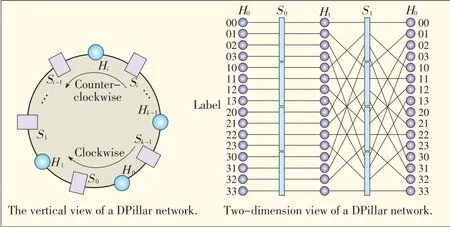
▲Figure9.DPillar topology.
The uFix proposed in[24]is a scalable and modularized architecture that interconnects heterogeneous data center containers(Fig.10).Every container can have a different structure,such as a fat-tree or BCube structure.In uFix,each server in a container reserves an NIC port for intercontainer connection.The uFix is defined iteratively;that is,a level l uFix domain comprises a number of level/-1 uFix domains.A server with a level/uFix link is called a level/uFix proxy.It routesbetween containers.
Wireless technology is also used in DCNs.In a typical data center,a data center rack comprises 40 servers connected to a top-of-rack(ToR)switch with 1G links.The ToR switch is connected to the aggregation switch via a 10G link.Thus,the links from ToRs to aggregation switches are oversubscribed by a ratio of 1:4.These up-links are the potential hotspots that hinder network performance.Rather than adding wired links to the network,multigigabit wireless links have been proposed to provide additional bandwidth[25].Each ToR switch has one or more 60 GHz wireless device with electronically steerable directional antennas.A central controller monitor switches the beams of the wireless devices to set up flyways between ToR switches.Theseflywaysprovideadded bandwidth asneeded.
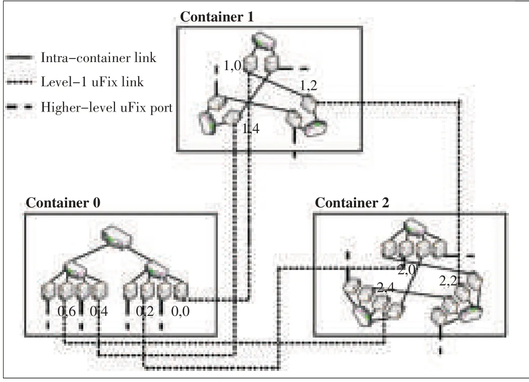
▲Figure10.uFix topology.
3.5 Comparisons
Most of today's data centers are based on switch-centric architectures.Although their scalability and flexibility is not good enough,switch-centric architectures have inherent advantages:They are similar to traditional network architectures,so it is easier to upgrade traditional switches to support these new architectures.Most network components and protocols can be directly used in new architectures or can be used with slight modification.Server-centric architectures eliminate switch restrictions so that routing and scaling up is easier.New featuresand functions can be flexibly added on the servers.However,theintricatenetwork topology,bandwidth bottleneck,lower packet-routing speed,and occupation of the server resource are all drawbacks.
An arbitrary,irregular network structure is flexible and has good scalability,but it is unlikely to be applied in a large data center becauseit isvery difficult tomanageand maintain.
4 VM Migration
In section 3,we introduced state-of-the-art solutions to network scalability.With these new network structures,large networks with tens to hundreds of thousands of servers can be built out.To provide the huge bandwidth needed in data centers,multiple paths are deployed between any pair of servers.To fully use these paths,layer-3 routing is used in these solutions.
Layer-3 routing limits the VMmigration within a single layer-2 domain.However,to take full advantage of virtualization,it is desirable that VM can migrate anywhere in the data center.That means that the entire DCN looks like a single layer-2 subnet,at least from the perspective of end users,that is,VMs.To solve this problem,big layer-2 network solutions havebeen proposed.
4.1 Device Virtualization
One such solution isdevice virtualization technology.Multiple switches are virtualized into one logical switch,and multiple links are aggregated into one link.H3C's IRF technology[26](Fig.11)and the Cisco's VSStechnology are examples of device virtualization technology.With such technology,a multiroot tree with loops is re-formed into a simple one-root tree without loops,and all the links are fully utilized.Otherwise,STP blocks the redundant links to eliminate loops in network.Aggregation technologies are relatively mature and have been used in practice.However,they use private enterprise protocols that have poor interoperability;they are difficult to automatically configure;and their supported networks are not very large.
4.2 Layer-2 Routing
Device virtualization technology can be used only in small or medium-sized data centers.To support large networks,layer-2 routing has been proposed.In the layer-2 switching,layer-3 routing technology,such as TRILL[27]and Cisco's FarbricPath[28],is applied.TRILL is an IETF standard that is used in devices called RBridges(routing bridges)or in TRILL Switches,which provide multipath forwarding for Ethernet frames.TRILL applies an IProuting mechanism in the Ethernet frames'forwarding.In TRILL,RBridgescomputetheshortest path and equal-cost paths in layer-2 by using TRILL IS-IS,which is a link-state routing protocol similar to IS-IS routing protocol.MAC-in-MAC packets are forwarded to the destination host via the switched network comprising RBridges.FabricPath is a similar(but private)technology provided by Cisco.
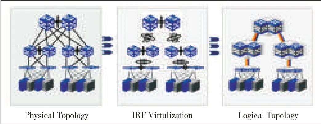
▲Figure11.IRF-based network without STP.
Another layer-2 routing solution is SEATTLE,which uses link-state routing protocol to establish a routing path between switches[29].Unlike TRILL,SEATTLE uses the global switch-level view provided by a link-state routing protocol to form a one-hop DHT.This DHT stores the IP to MAC mapping and MACto host location mapping of each host in switches.SEATTLE converts an ARP request into a unicast-based message to obtain the destination host's MACaddress.It then determinesitslocation accordingtothe MACaddress.
4.3 Offline Routing
Layer-2 routing technologies put no requirements on the network structure and can be used in large DCNs.However,they import a routing protocol into the layer-2 network.Such a protocol is difficult to implement on switches and increases the complexity of the control plane.New switches should be developed for the new layer-2 routing protocol.SPAIN[30]and Net-Lord[31]demonstrate new thinking about layer-2 interconnection based on existing switch devices in an arbitrary topology.With these methods,a set of paths is pre-computed offline for each pair of source-destination hosts by exploiting the redundancy in a given network topology.Then,these paths are merged into aset of trees,and each treeismapped onto aseparate VLAN.In this way,a proxy application is installed on the hosts,and the proxy chooses several VLAN paths to transmit packets to the destination host.The advantage of this is that multipath isimplemented,and routing load isbalanced on multiple paths in an arbitrary topology.Its drawbacks are inflexibility to changes in topology and required modifications to hosts.
4.4 Topology-Aware Routing
The previously mentioned technologies are versatile and are applicable to any network structure;however,specialized routing protocolsare required sothat they can learn the network topology.In contrast,PortLand is a big layer-2 network solution specifically for the fat-tree network[32].It uses a lightweight location discovery protocol(LDP)that allows switches to discover their location in the topology.In PortLand,every end host is assigned an internal pseudo MAC(PMAC)that encodes the location of the end host.Compared with the other layer-2 technologies,PortLand leverages the information of network structure within layer-2 routing.
4.5 Discussion
We have introduced some big layer-2 network solutions for VM migration and discussed their features.Each solution has its own advantages and disadvantages and is suitable for certain environments.More research has to be done to find more general,
better-performingsolutionsfor VMmigration.
Ideally,a big layer-2 solution for VM migration should be simple and efficient.It should be easy to implement and should involve less importation of new technologies and less device modification.Efficiency implies rapid forwarding with less overhead.Because regular topologies are used in most data centers,leveraging the topology's regularity simplifies the VM migration solution and makes it more efficient.It is better if such a topology-centered solution can be applied to any topology with some regularity.The previously-mentioned solutions blend packet routing with VM migration,which makes them more complicated.We suggest VM migration should be separated from network routing,and overlay on the network routing,like NVO3[33].NVO3,VXLAN[34],and NVGRE[35]are some multitenancy solutions for data centers.They can be used to solve VM migration problems as well.However,because these solutions are not very mature,we will not discussthemhere.
5 Related Works
As well as research on the network architecture itself,other research on architecture-related areas such as network performance,energy-saving,and configuration hasbeen done.
In[36],the performance of FiConn[17]and fat-tree network architectures are compared through experimentation.In these experiments,a three-tier transaction system is deployed on the two types of networks.The results show that FiConn performs better than fat-tree in terms of throughput because the traffic between two virtual machines must pass through the upper switches in fat-tree.Fat-tree results in better network reliability and stability.When routing nodes break down in a FiConn network,network performancedeclinessignificantly.
Some works leverage the network structure to improve overall network performance.In[37],a VM migration scheme is proposed to avoid network overload caused by VM migration.Inter-VM dependencies and underlying network topology are incorporated into VM migration decisions.In [38],a source-to-receiver expansion approach based on regular topology isused tobuild efficient multicast treesand routing.
In some works,the network is slightly modified to save energy.ElasticTree continually monitors data center traffic and calculates a subnet that covers all the traffic and meets network performance and fault tolerance targets[39].Then,it powers down the other unneeded links and switches to save energy.Honeyguide saves energy by means of VM migration[7].It moves the VMs together in order to increase the number of unused servers and then powers down these servers and related unused switches and links.To improve network fault tolerance,bypass linksare added between upper-tier switchesand physical servers.
In[40],a generic and automatic address configuration system for data centers is proposed.In[41],a new layer-2 for data centers is proposed.This layer comprises interconnected policy-aware switches,and middleboxes,such as firewalls and load balances,intothoseswitchesthat areoff thenetwork path.
Much research has been done on all aspects of DCNs;however,wedonot introduceit all here.
6 Conclusion
Cloud computing services have created new challenges in data centers.Next-generation data centers will require large networks with more internal bandwidth.Moreover,data centers will need to support free VM migration across the entire DCN.Thesefeatureswill require DCNstohavenew architectures.
In this paper,we have described the latest research on DCN architecture.We have classified these architectures and determined their features and differences.This paper is intended to inform readers about the newest research in DCN architecturesothat breakthroughsmay bemadein thisfield.
Many kinds of architectures have been proposed to solve problems in existing data centers.These architectures have their own advantages,and different data centers use different architectures depending on their supported applications.We suggest further research on the general routing method compatible with different network architectures.This method should fully capitalize on the regular network topology.We also suggest further research on separating VM migration from network routing.Finally,we suggest further research into areas such as QoSand VMmigration policiesthat arerelated totopology.
Acknowledgements
We thank Xiaoli Song and Bin Liu of ZTE Inc.for their great support and help to this paper.This work is supported by the ZTE-BJTU Collaborative Research Program under Grant No.K11L00190 and the Fundamental Research Funds for the Central Universitiesunder Grant No.K12JB00060.
- ZTE Communications的其它文章
- ZTEConverged FDD/TDDSolution Wins GTIInnovation Award
- Introduction to ZTECommunications
- Android Apps:Static Analysis Based on Permission Classification
- FBAR-Based Radio Frequency Bandpass Filter for 3GTD-SCDMA
- Battery Voltage Discharge Rate Prediction and Video Content Adaptation in Mobile Deviceson 3G Access Networks
- An Improved Color Cast Detection Method Based on an AB-Chromaticity Histogram

