Effects of Reynolds Number on the Hydrodynamic Characteristics of Heave Damping Plate
TIAN Xin-liang,YANG Jian-min,LI Xin,SHEN Yu-gao
(State Key Laboratory of Ocean Engineering,Shanghai Jiao Tong University,Shanghai 200240,China)
1 Introduction
Deepwater offshore structures at sea,e.g.a Spar platform and a tension leg platform(TLP),may experience motion responses due to incident wave forces[1-2].The motion in vertical direction,i.e.heave motion,is specially concerned by engineers because large heave motion may cause damages in risers,drilling pipes and mooring lines.Heave damping plates are installed in Spar platforms and they have been demonstrated as an effective way to minimize the heave response[3-5].The heave damping plates significantly increase the heave added mass of the platform.Therefore,the natural frequency of heave motion is decreased and be moved further out of the wave-frequency region of significant wave energy to avoid resonance.On the other hand,heave damping plates could provide extra damping forces in heave due to vortex shedding at the edges of the plates[1].
Model test in wave basin is a classic and widely recognized way to investigate and estimate the hydrodynamic performance of floating offshore structures.Generally,the platforms are scaled to model size based on the geometric similarity and Froude similarity(i.e.gravity similarity)while the Reynolds similarity(i.e.viscous similarity)is not able to be satisfied[6].However,for the heave damping plates in Spar platform which are often located under the water surface as deep as 100 meters,the effects of free surface waves could be eliminated and the viscous effects which are closely related with the flow separation and vortex shedding phenomena start to play the major role in characterizing the hydrodynamic performance of heave damping plates.The Reynolds number in model tests is about two orders lower in magnitude than that in the prototype[7].Although many experimental[1,3-5,7-11]and numerical[4,12-18]studies on the hydrodynamic characteristics of heave damping plates have been carried out in the past two decades,their studies mainly focused on the geometric configurations of the heave damping plates,e.g.size of plates[9],distances between plates[4,15],thickness[9,11],porosity[1,3,5,13,19]and taper angles[18],etc.To our best knowledge,the effects of Reynolds number on the hydrodynamic characteristics of heave damping plates have not been well documented and studies on this issue are awaited.
The present study aims to investigate the effects of Reynolds number on the heave damping plates with the technique of Computational Fluid Dynamics(CFD)using large-eddy simulation(LES)method.We consider a thin circular disk which is forced to oscillate sinusoidally along its axis in a fluid at rest.The axis velocity of the circular disk is as a function of time:uz(t)=Umaxcos( 2πt/T),where z represents the axis direction,Umaxis the maximum speed of the oscillation motion,T is the period of the oscillation and t is the time.The key dimensionless parameters characterizing the flow features are the Reynolds number(Re)and Keulegan-Carpenter number(KC).The definitions of Re and KC are given as:

where D is the diameter of the disk,ν is the kinematic viscosity of the fluid and a is the amplitude of the oscillation motion.Following the nomenclature proposed by Sarpkaya[20],we can also obtain the frequency number

Therefore,for a fixed KC number,the effect of Reynolds number(Re)is equivalent to the effect of β.
In this study,we investigate the cases at KC=0.2,0.6 and 1.0,respectively.For each KC number,five β numbers,i.e.β=8×102,8×103,8×104,8×105and 8×10⁶,are considered respectively.Therefore,the Reynolds number considered in this study ranges from O(102)to O(107),which covers the Reynolds number region of heave damping plates in both wave basin model tests and prototype.
The remainder of this paper is organized as follows.The mathematical formulations and numerical methods used in the present study are given in chapter 2.Computational overview,convergence and validation studies are presented in chapter 3.The results and discussions are described in chapter 4.Finally,some concluding remarks are given in chapter 5.
2 Mathematical formulations and numerical methods
2.1 Mathematical formulations
In this study,the numerical simulations are carried out with the large-eddy simulation method,in which large-scale motions are explicitly computed and small-scale eddies are modeled with a subgrid scale(SGS)model in order to represent the effects of unresolved motions on the resolved scales.A filtering is introduced to decompose the variable φ into the sum of a filtered componentnd a subgrid scale component φ′,i.e. φ=+φ′.By applying the filtering operation to the Navier-Stokes(N-S)equations for an incompressible flow,the filtered NS equations can be expressed as follows:

where i,j=1-3;x1,x2and x2(or x,y and z)denote three coordinates in Cartesian coordinate system;are the corresponding resolved velocity components;ρ is the density of the fluid;is the resolved pressure;and the subgrid stress τis given byij

The first term on the right-hand side of equation(6)can not be computed directly from equations(4)and(5),thus τijmust be modeled in order to close the equations.The SGS model proposed by Smagorinsky[21]is used in the present study,and τis written asij

where δijis the Kronecker delta;=0.5 (∂ui/∂uj+∂uj/∂ui)is the strain rate in the resolved velocity field;νtis the subgrid eddy viscosity.
Using dimensional analysis,the eddy viscosity νtcan be calculated by the following formula

where the constant Cs=0.2;Δ is the filter-width.In this study,the Van Driest damping function proposed by Van Driest[22]is applied;is the cubic root of the mesh cell volume;κ=0.41 is the von Kármán constant;CΔ=0.158;A+=26;n is the wall normal distance;n+is the nondimensionalized wall normal distance,taken as n+=u*n/ν,where u*is the wall friction velocity;
2.2 Numerical methods
The open source CFD code OpenFOAM is used here to solve the equations described in chapter 2.1.OpenFOAM is mainly applied for solving problems in continuum mechanics.It is built based on the tensorial approach and object oriented techniques[23].The PIMPLE algorithm which merged PISO(Pressure Implicit with Splitting of Operators)and SIMPLE(Semi-Implicit Method for Pressure-Linked Equations)is used in the present study.The spatial schemes for interpolation,gradient,Laplacian and divergence are linear,Gauss linear,Gauss linear corrected and Gauss linear schemes,respectively.All these schemes are in second order.The second order Crank-Nicolson scheme is used for the time integration.Further details of these schemes are given in OpenFOAM[24].
3 Computational overview,convergence and validation studies
3.1 Computational overview
A spherical computational domain is used in this study and the circular disk locates at the center of the computational domain,see Fig.1(a).The diameter of the computational domain is 40 D,which is large enough to eliminate the effects of far field boundaries on the calculated results.The origin of the coordinates locates at the center of the disk and the z-axis coincides with the axis of the disk.On the disk surface,no-slip boundary condition is specified for the velocity and the pressure is set as zero normal gradient.At the outer boundary,the velocity is set as zero normal gradient and the pressure is fixed at zero.The whole computational domain is discretized with hexahedral elements,and the grid near the disk surface is refined in order to resolve the steep gradient there.Fig.1(b)shows the mesh structures on the disk surface.The thickness of the disk is 0.02 D.
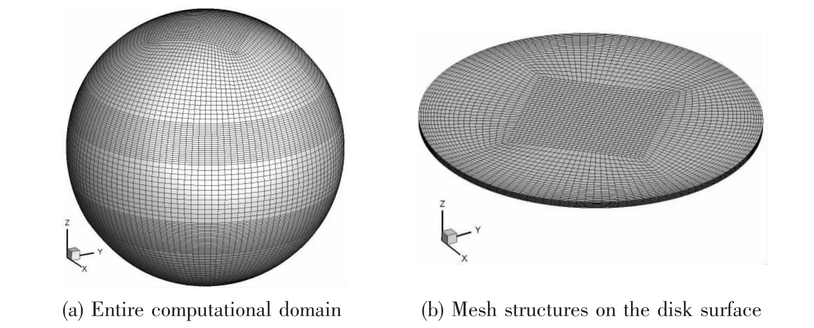
Fig.1 Computational domain and mesh structures overview
The oscillation motion of the circular disk is simulated by using the deforming mesh technique.The grid points relocate at each time step in a spring-like way and the topology of the mesh does not change during the simulation in order to sustain a good mesh quality.
The computations are carried out on the TH-1A system in National Supercomputer Center in Tianjin.The parallel computing technique is adopted and the computational domain is divided into 36 subdomains.Each case runs for 15 periods of oscillations and the results presented in this paper are calculated from the latest 10 cycles,this is to eliminate the transient effects at the beginning of the calculations.
3.2 Convergence and validation studies
To assert the effects of grid and time resolutions on the calculated results,the grid and time step convergence studies are carried out for the case at KC=0.2 and β=8×10⁴.The main characteristics of three typical configurations with different grid resolutions and time steps are shown in Tab.1,where n1represents the height of the first node away from the disk surface,Δt is the time step.
Fig.2 shows the time histories of the axis drag force coefficient(Cz)on the disk obtained from the cases with different configurations as well as the comparison with the experimental measurement by Tao and Dray[1].Here Czis defined as

Tab.1 Details of the cases with different grid and time resolutions

where Fz(t) is the axis force acting on the disk and it is directly calculated by integrating the pressure and viscous shear stress over the disk surfaces;S is the projected area of the disk,taken as S=πD2/4.As shown in Fig.2,the results for the cases with Set-II and Set-III collapse together,indicating a reasonable convergence for the special and time resolutions.To make the calculations accurate,Set-III with 1 329 152 mesh elements and a time step of T/5 000 is used for the cases with other KC and β numbers.
Furthermore,the experimental results obtained by Tao and Dray[1]are reproduced and repeated in each period in Fig.2 for comparison.It appears that the present calculated results agree well with the experimental measurements by Tao and Dray[1].It is reported that the phase lag between the axis force and the displacement is crucial in determining the energy transfer to the fluid due to the small magnitude of damping force[1].He[11]also emphasized that the ac-curate measure in the phase lag between the axis force and the displacement is the key to the successful measurement of damping coefficient.Fortunately,the calculated phase by the present simulation is in good agreement with the experimental results by Tao and Dray[1],see Fig.2.Therefore,it is concluded that the present numerical approach can provide satisfactory results for the heave damping plate.
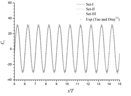
Fig.2 Time histories of the axis drag force coefficient on the disk at KC=0.2 and β=8×10⁴.
4 Results and discussions
4.1 Hydrodynamic force coefficients
The hydrodynamic added mass coefficient(Ca)and damping coefficient(Cd)are the two key parameters regarding the hydrodynamic characteristics of the oscillating structures.In this study,Caand Cdare calculated from the axis force histories by Fourier analysis,as follows[25]:

where∀is the immersed volume of the disk;ω is the angular frequency of the oscillation,here ω=2π/T.
Following the formulations proposed by Tao and Dray[1],the hydrodynamic force coefficients(Caand Cd)are further nondimensionalised with respect to the theoretical ideal fluid added mass of a disk,m′=1/3ρD3.Hence,the added mass and damping coefficients are rewritten,respectively,as:

Fig.3 shows the variations of added mass coefficient(A′)with respect to the frequency number(β).It is observed that A′increases as KC increases in the considered KC region(0.2≤KC≤1.0),i.e.large oscillation motion results in large added mass.This is consistent with the measurements by Tao and Dray[1],but in contrast to the potential solution[13]which gives constant added mass(A′=1)independent of KC.For the cases at KC=0.2 and β<104,A′decreases as β increases,and A′appears independent of β as β>104.For the cases at KC=0.6 and 1.0,A′increases as β increases when β<105.Similar with that of KC=0.2,A′for KC=0.6 and 1.0 becomes less sensitive to the variations of β for high β values.For the heave damping plates in Spar platform at sea,the frequency numbers(β)are in the order of O(106-7),while the model tests carried out in wave basins are usually at β~O(104-5).Effects of β on A′are getting weaker as β increases,and the added mass in the model test carried out is approximately equivalent to that in the prototype Spar at sea.
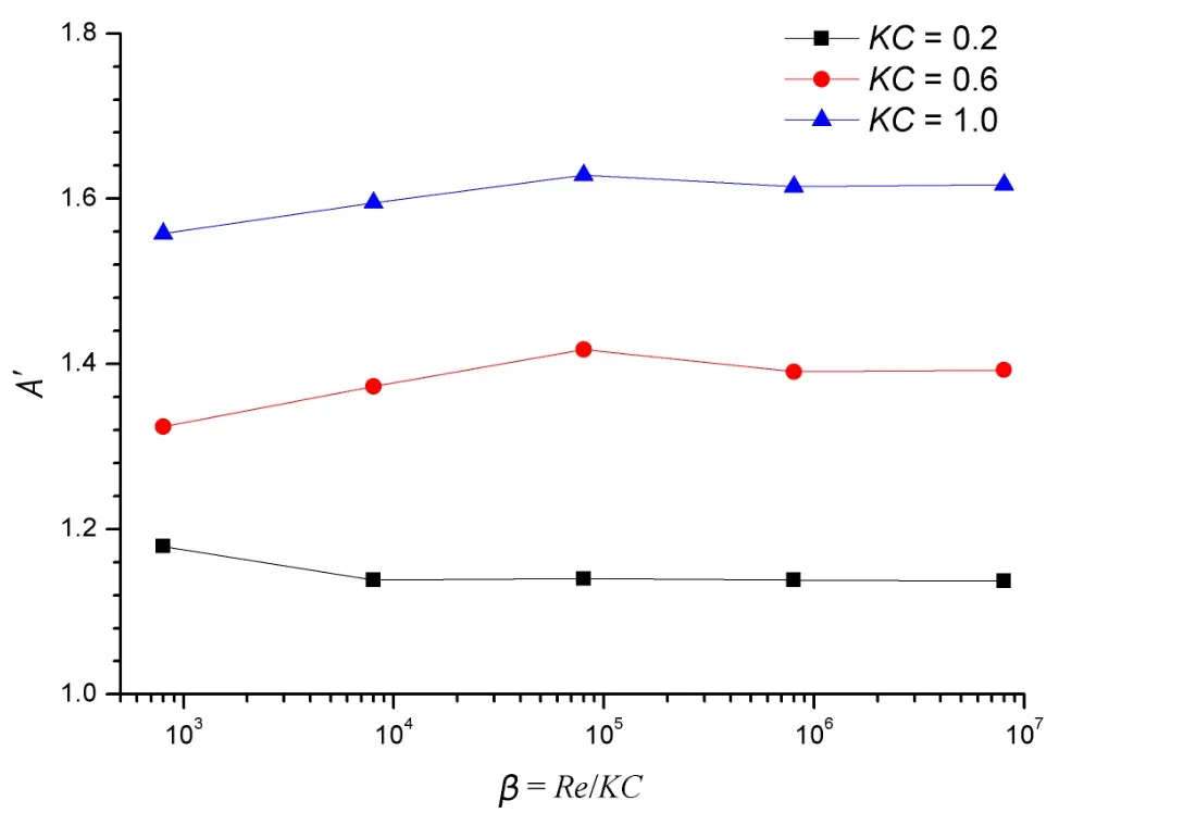
Fig.3 A′versus β for the oscillating disk at KC=0.2,0.6 and 1.0
Fig.4 shows the variations of damping coefficient(B′)versus frequency number (β)at various KC numbers.As shown in Fig.4,B′increases as KC increases,this is again consistent with the measurements by Tao and Dray[1].It appears that the effects of β on B′is small.Therefore,the damping coefficient B′of heave damping plate in the wave basin model tests is equivalent to that in the prototype Spar at sea.
Overall,unlike the case of a circular cylinder,the added mass and damping coefficients of heave damping plates are not so sensitive to β for a given KC.This is because the flow separation point is fixed at the edge of the heave damping plate but varies along the surface of the circular cylinder.It is good news for wave basin model test that the Reynolds number effects(scale effects)are minimized in the case of a heave damping plate.Therefore,the heave damping plate in Spar platform could be scaled to model size by simply following the geometric similarity law.
4.2 Vortical structures
Characteristics of the hydrodynamic forces on the disk are closely related with the features of the flow around the disk.The vortical structures are investigated in this section for better understanding the underlying physics in the hydrodynamic mechanism of the heave damping plate.Tab.2 shows the instantaneous vortical structures around the disk for all the considered cases in this study,i.e.the cases at KC=0.2,0.6,1.0 and β=8×102,8×103,8×104,8×105and 8×10⁶.The deep dark region in each picture represents the heave damping plate.Here the vortical structures are identified by the iso-surface of the Q-criterion[26]

where S and Ω denote the strain and the rotation tensor,respectively.The instantaneous flow was obtained at t=T/4,i.e.the disk reaches the maximum displacement with respect to the mean position.
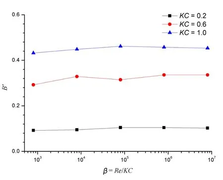
Fig.4 B′versus β for the oscillating disk at KC=0.2,0.6 and 1.0
As shown in Tab.2,the flow is approximately axisymmetric when β=8×10²,and the vortical rings are formed due to the laminar vortex shedding.For the cases at β≥8×10³,significant non-axisymmetric vortical structures are observed,and the flow is indeed turbulent.As it has been shown in Figs.3 and 4 that the variations of added mass and damping coefficients are not very sensitive to the variations of β,it appears that the effect of turbulent fluctuations on the disk is averaged over the surface of the disk.A similar turbulent fluctuation averaging effect is observed in the process of the thermal convection in a water tank with a freely floating plate[27].In other words,though the flow at high β numbers is actually turbulent,the hydrodynamic forces acting on the disk is equivalent to that at low β numbers where the flow is laminar and axisymmetric.Therefore,it means that one can obtain reliable force results by simplify the non-axisymmetric turbulent flow into an axisymmetric flow.This is of great significance in engineering applications that a simplified axisymmetric problem could be solved using twodimensional(2D)numerical simulations which requires much fewer computational resources compared with the three-dimensional(3D)computations.There have been some 2D numerical simulations carried out with success by using this simplification[14,16].However,it should be noted that great attentions should be paid while interpreting the flow features and vortex shedding/interaction modes,because flow around the structures at high β numbers are actually nonaxisymmetric and turbulent.
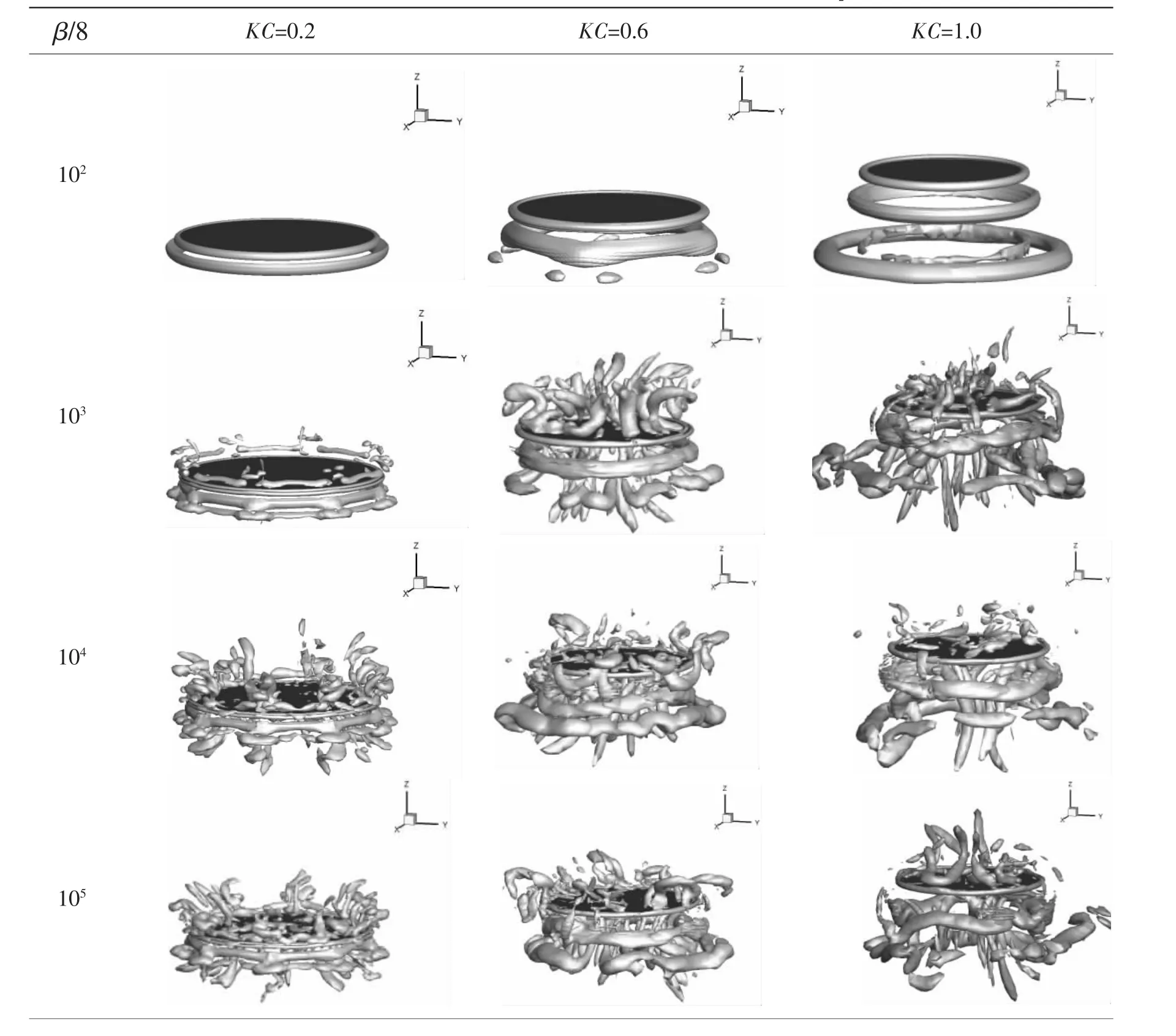
Tab.2 Vortical structures of the cases with various KC and β numbers at t=T/4

Continue 2
5 Conclusions
Three-dimensional numerical simulations for a thin circular disk oscillating sinusoidally along its axis in a fluid at rest have been performed with the large-eddy simulation method.Fifteen typical cases are investigated at KC=0.2,0.6,1.0 and β=8×102,8×103,8×104,8×105and 8×10⁶,resulting a Reynolds number in the range of 1.6×10²≤Re≤8×10⁶.The effects of β(or Re)on the added mass coefficient,damping coefficient and the vortical structures are investigated.The main conclusions are summarized as follows:
(a)Both added mass and damping coefficients increase as KC increases in the range of 0.2≤KC≤1.0.For a given KC number,the effects of β(or Re)on the added mass and damping coefficients are actually not significant.The scale effects are minimized in the case of heave damping plate and the heave damping plate in Spar platform could be scaled to model size simply following the geometric similarity law.
(b)Flow around the disk is approximately axisymmetric at β=8×10²,and the flow becomes non-axisymmetric and turbulent when β≥8×10³.
(c)The effects of turbulent fluctuations on the hydrodynamic forces on the disk are averaged over the disk surface,thus the hydrodynamic force coefficients on the circular disk at high Reynolds number could be calculated by solving the simplified problem based on the axisymmetric flow assumption.
Overall,this paper presents a detailed investigation on the effect of Reynolds number on the hydrodynamic forces on the heave damping plate and flow features around the heave damping plate.These findings are of practical significance in both wave basin model tests and numerical simulations for heave damping plates.
[1]Tao L,Dray D.Hydrodynamic performance of solid and porous heave plates[J].Ocean Engineering,2008,35(10):1006-1014.
[2]Wang Y,Yang J,Hu Z,Xiao L.Theoretical research on hydrodynamics of a geometric spar in frequency-and time-domains[J].Journal of Hydrodynamics,Ser B,2008,20(1):30-38.
[3]Downie M J,Graham J M R,Hall C,Incecik A,Nygaard I.An experimental investigation of motion control devices for truss spars[J].Marine Structures,2000,13(2):75-90.
[4]Magee A,Sablok A,Maher J,Halkyard J,Finn L,Datta I.Heave plate effectiveness in the performance of truss spars[C]//In:Proceedings of ETCE/OMAE2000 Joint Conference Energy for the New Millenium,February 14-17 2000.New Orleans,LA:ASME,2000.
[5]Zhang F.Concept design and research on hydrodynamics of Spar plateform[D].Shanghai:Shanghai Jiao Tong University,2008.
[6]Gao Q,Zhou L.Numerical simulation of scale effect on ship stern flow and hydrodynamic performance[J].Journal of Hydrodynamics,Ser B,1995,3(1):56-64.
[7]Prislin I,Blevins R D,Halkyard J E.Viscous damping and added mass of solid square plates[C]//In:17th International Conference on Offshore Mechanics and Artic Engineering.ASME,Lisbon,1998.
[8]Lake M,He H,Troesch A W,Perlin M,Thiagarajan K P.Hydrodynamic coefficient estimation for TLP and Spar structures[J].Journal of Offshore Mechanics and Arctic Engineering,2000,122:118-124.
[9]Thiagarajan K P,Datta I,Ran A Z,Tao L,Halkyard J E.Influence of heave plate geometry on the heave response of classic spars[C]//In:Proceedings of OMAE’02 21st International Conference on Offshore Mechanics and Artic Engineering,June 23-28 2002.Oslo,Norway:ASME,2002.
[10]Thiagarajan K P,Troesch A W.Effects of appendages and small currents on the hydrodynamic heave damping of TLP columns[J].Journal of Offshore Mechanics and Arctic Engineering,1998,120:37-42.
[11]He H.Hydrodynamics of thin plates[D].University of Michigan,USA,2003.
[12]Holmes S,Bhat S,Beynet P,Sablok A,Prislin I.Heave plate design with computational fluid dynamics[J].Journal of Offshore Mechanics and Arctic Engineering,2001,123:22-28.
[13]Molin B.On the added mass and damping of periodic arrays of fully or partially porous disks[J].Journal of Fluids and Structures,2001,15(2):275-290.
[14]Tao L,Cai S.Heave motion suppression of a Spar with a heave plate[J].Ocean Engineering,2004,31(5-6):669-692.
[15]Tao L,Molin B,Scolan Y M,Thiagarajan K.Spacing effects on hydrodynamics of heave plates on offshore structures[J].Journal of Fluids and Structures,2007,23(8):1119-1136.
[16]Tao L,Thiagarajan K.Low KC flow regimes of oscillating sharp edges.II.Hydrodynamic forces[J].Applied Ocean Research,2003,25(2):53-62.
[17]Tao L,Thiagarajan K.Low KC flow regimes of oscillating sharp edges I.Vortex shedding observation[J].Applied Ocean Research,2003,25(1):21-35.
[18]Shen W,Tang Y,Liu L.Research on the hydrodynamic characteristics of heave plate structure with different form edges of a Spar platform[J].China Ocean Engineering,2012,26(1):177-184.
[19]Wu W,Miao Q,Kuang X,Yang S,He Z.Research on hydrodynamic characteristics of forced oscillation heave damping plates of Spar platforms[J].Journal of Ship Mechanics,2009,13(001):27-33.
[20]Sarpkaya T.Force on a circular cylinder in viscous oscillatory flow at low Keulegan-Carpenter numbers[J].Journal of Fluid Mechanics,1986,165(1):61-71.
[21]Smagorinsky J.General circulation experiments with the primitive equations[J].Monthly Weather Review,1963,91(3):99-164.
[22]Van Driest E R.On turbulent flow near a wall[J].Journal of Aerospace Science,1956,23:1007-1011.
[23]Weller H G,Tabor G,Jasak H,Fureby C.A tensorial approach to computational continuum mechanics using object-oriented techniques[J].Computers in Physics,1998,12:620.
[24]OPENFOAM:The Open Source CFD Toolbox,Programmer’s Guide,Version 1.6[M]:OpenCFD Limited,2009.
[25]Sarpkaya T,Isaacson M,Isaacson M S Q.Mechanics of wave forces on offshore structures[M]:Van Nostrand Reinhold New York,1981.
[26]Hunt J C R,Wray A A,Moin P.Eddies,streams,and convergence zones in turbulent flows[C].In:Center for Turbulence Research Report CTR-S88,1988:193-208.
[27]Zhong J Q,Zhang J.Thermal convection with a freely moving top boundary[J].Physics of Fluids,2005,17:1-12.

