
A model test system with a dynamic load device for geotechnical engineering in cold regions
2012-12-09 09:37:04ShuPingZhaoWeiMaGuiDeJiaoFeiLuo
ShuPing Zhao , Wei Ma , GuiDe Jiao ,2, Fei Luo
1. State Key Laboratory of Frozen Soil Engineering, Cold and Arid Regions Environmental and Engineering Research Institute,Chinese Academy of Sciences, Lanzhou, Gansu 730000, China.
2. Civil and Engineering Department, Lanzhou University, Lanzhou, Gansu 730000, China.
A model test system with a dynamic load device for geotechnical engineering in cold regions
ShuPing Zhao1*, Wei Ma1, GuiDe Jiao1,2, Fei Luo1
1. State Key Laboratory of Frozen Soil Engineering, Cold and Arid Regions Environmental and Engineering Research Institute,Chinese Academy of Sciences, Lanzhou, Gansu 730000, China.
2. Civil and Engineering Department, Lanzhou University, Lanzhou, Gansu 730000, China.
A model test system with a dynamic load device for geotechnical engineering in cold regions is presented. This system consists of a model test tank, a refrigeration device and temperature controller, a dynamic load device, together with sensors and data loggers for detecting stress, deformation, and temperature changes. The system can accommodate soil blocks up to 3 m in length, 2.5 m in width, and 1 m in height. The lowest temperature provided by the refrigeration device is -20 °C. The maximum load provided by the dynamic load device is 100 kN and the vibration frequency of the dynamic load can range from 0.1 to 10 Hz. A number of waveforms, such as sine waves, rectangular waves, triangle waves, and other user-defined waves can be generated by the dynamic load device controller.
model test system; dynamic load device; stress; deformation; temperature change
1. Introduction
Dynamic loading should be considered for engineering and construction in cold regions. Earthquakes will cause dynamic loading and can result in structural damages, while traffic loading produces long-term dynamic loading that will affect long-term stability of roadbeds. Model testing has several advantages, including being relatively rapid, low-cost,and highly controllable. These features can avoid many problems encountered in field testing, such as expensive research expenditures, too many influence factors, physically-hard environments and complex conditions, and long observation period. Thus there are many benefits in using an advance model test system to perform geotechnical engineering tests under dynamic loading, and to study dynamic stress, deformation, and temperature change of frozen soil.
There is a large-scale model laboratory (3,000 m2) for frozen soil engineering at the U.S. Army Cold Regions Research and Engineering Laboratory (CRREL) in Hanover,New Hampshire. Its main task is to study the influence of cold region environments on all kinds of engineering construction, such as basements, roads, underground buildings,and so on. However, there is no dynamic load device in this system. Institute of Low Temperature Science Research,Hokkaido University of Japan developed a small model test system for oil and gas transport pipelines in cold regions. It can be used to conduct certain mechanical research but does not have a dynamic load device. China University of Mining and Technology has a model test system with a simple load device to simulate freezing construction methods in mining engineering (Zhouet al., 1999). Small-scale and middle-scale model test systems without load devices were established by the State Key Laboratory of Frozen Soil Engineering, Chinese Academy of Sciences (Yuet al., 2002;Bing, 2008). Xi’nan Jiaotong University developed a large-scale model test system to study the dynamic stability of roadbeds (Cao and Cai, 1996, 2006; Su and Cai, 2001;Tanget al., 2006; Liu and Chen, 2008), while Chinese Railway Science Research Institute developed a small-scale test system to simulate roadbed vibration (Maet al., 2006;Donget al., 2010). However, both systems lack a temperature control system and cannot be used to simulate engineering in cold regions. Given this situation, we develop a model test system with a temperature control system and a dynamic load device, which is useful for dealing with the major engineering problems in cold regions, namely, dynamic response, frost heaving, and thaw settlement.
2. Design of the model test system
The model test system consists of a model test tank, a dynamic load device, a refrigeration device and temperature controller, together with sensors and data loggers.
2.1. Model test tank
Many factors have to be considered when building the model test tank. First, the model test tank must be heat-insulated. Second, it must be able to support the use of a dynamic load device, a refrigeration device and temperature controller. Additionally, it has to be convenient to load and unload soil samples and to assemble all kinds of sensors,data loggers, and cables. Figure 1 shows the schematic diagram of our model test tank, which meets all these criteria.Its specific features are described as follows.
(1) The model test tank, including four lateral walls and one underside wall, is made of reinforced concrete. The steel bars in all the walls are woven into a cage so the lateral and underside walls are linked into a unity. The shapes of the lateral walls, I and III, are rectangular. The height of wall I is same as that of soil in the tank, which is less than the height of wall III. The lateral walls II and IV have taller extensions reinforced with steel bars and thus are used to support the load-bearing beam of the dynamic load device. Holes are arranged at various locations on wall I to install sensors, data loggers, and cables.
(2) Polyurethane heat-insulated material is installed around the lateral walls and a waterproof layer is installed under the underside wall. Large heat-insulated upper cover plates are installed on the top of the model test tank. The entire design provides a good heat preservation effect.
(3) The large heat-insulated upper cover plates consist of four pieces. A 1-m square hole is cut into the center of the large upper cover plates to accommodate the small heat-insulated cover plate on the dynamic load device. A heat-insulated baffle plate is placed on wall I.
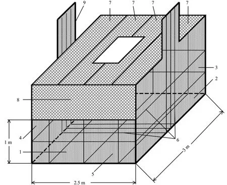
Figure 1 Schematic diagram of the model test tank (1: lateral wall I; 2: lateral wall II; 3: lateral wall III; 4: lateral walls IV;5: underside wall; 6: steel bars; 7: large heat-insulated upper cover plates; 8: heat-insulated baffle plate;9: support for the load-bearing beam of the dynamic load device)
2.2. Dynamic load device
The vertical profile of the model test tank and the dynamic load device are shown in Figure 2. The specific features of the dynamic load device are described as follows.
(1) The load-bearing beam of the dynamic load device is large-span and fits with the width of the model test tank. It has high stiffness (10,000 kN/mm) as well, which ensures that deformation and bending of the beam will not occur while applying dynamic loads. In the taller extensions of lateral walls II and IV, four fixed bolts with hooks in the bottom ends are embedded, which hook into the steel bar cage. The upper ends of the fixed bolts extend from the model test tank and are used to fix the load-bearing beam of the dynamic load device. The model test tank and the load-bearing beam constitute a reaction frame. Thus, while loading soil in the tank (which is equivalent to an action in the inner system), there will be no interference to the surrounding buildings and other test equipment.
(2) The two-way actuators and the loading rod are installed on the load-bearing beam. A 0.8-m square loading board is used to force loading and contact with soil. The connecting device connects the loading rod and the loading board. The loading board is fixed to the connecting device by an oblique rod, which increases the actual stiffness of the loading board and the uniformity of force applied on the soil.The upper end of the connecting device is concave and the bottom end of the loading rod is convex, so they can work together and prevent the loading rod from being resisted or damaged while the load is still partial.
(3) The 1-m square heat-insulated cover plate is set up on the load-bearing beam, whose position can be adjusted to work together with the large heat-insulated upper cover plates on the top of the model test tank. The actuator is located outside of the model test tank and is not affected by low temperature while the loading board is located inside the model test tank and can force a load on the frozen soil.
(4) The lifting device is attached to the building ceiling above the model test tank. It lifts the load-bearing beam while soil is put into the tank.
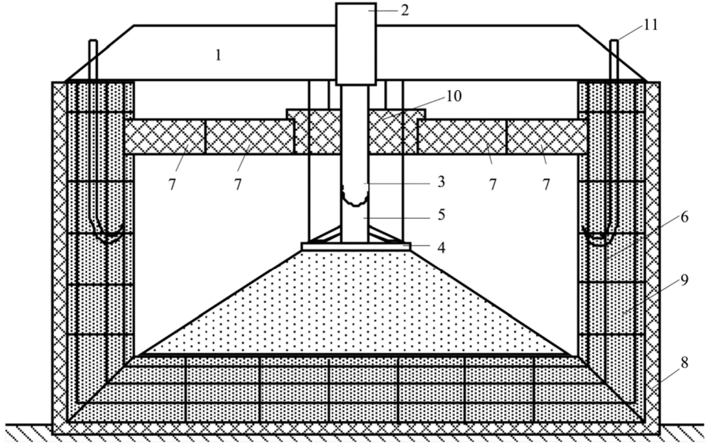
Figure 2 Vertical profile of model test tank and dynamic load device (1: load-bearing beam; 2: two-way actuator;3: loading rod; 4: loading board; 5: connecting device; 6: steel bars; 7: large heat-insulated upper cover plates;8: thermal insulation layer; 9: model test tank; 10: small heat-insulated cover plate; 11: fixed bolt)
2.3. Refrigeration device and temperature controller
Two devices are used to achieve accurate temperature control for large quantities of soil. The specific process is described as follows.
(1) The soil is put in the model test tank, which is heat-insulated.
(2) Three groups of freezing plates placed on the soil(top, lateral, and bottom) are used to rapidly lower the temperature of soil. Each group of freezing plates is connected to its own refrigeration device and temperature controller, so the temperature can be controlled independently. During the test, the temperature of each group of freezing plates can be set up according to the test requirements, so three boundary conditions can be formed.Figure 3 shows the schematic diagram of the model test soil and freezing plates.
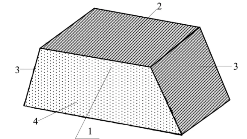
Figure 3 Schematic diagram of the model test soil and freezing plates (1: model test soil; 2: top freezing plate;3: lateral freezing plates; 4: bottom freezing plates)
(3) A flow channel inside each freezing plate is used to circulate freezing liquid (Figure 4). The temperature field of each freezing plate is uniform and stable. The principles of freezing and temperature control are shown in Figure 5 and described as follows.
The refrigeration device consists of an air compressor,condenser, fan, and pump. The refrigeration device cools the refrigerant in the evaporator. There is thermal exchange between the evaporator and the freezing liquid in the liquid storage tank. The low-temperature freezing liquid flows into the freezing plate and then cools the soil. For each group of freezing plates, two temperature sensors are utilized: one on the surface of the plate and the other inside the liquid storage tank. The data collected from these two temperature sensors are sent to the temperature controller, which controls the open degree of the electronic expansion valve according to the weighted average of temperature data. The open degree(0-100%) of the electronic expansion valve controls the flow of refrigerant, which will flexibly adjust the refrigerating capacity of the evaporator. Thus the temperature of the freezing liquid and freezing plate can be controlled precisely.
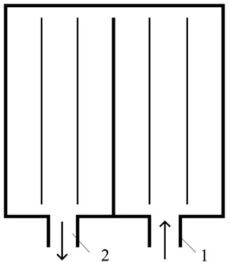
Figure 4 Plane profile of a freezing plate (1: inlet for freezing liquid;2: outlet for freezing liquid)

Figure 5 Schematic diagram of the principles of freezing and temperature control (1: refrigeration device; 2: freezing plate;3; temperature sensor; 4: temperature controller; 5: electronic expansion valve; 6: evaporator; 7: liquid storage tank)
2.4. Sensors and data loggers
The sensors used in this model test system include temperature sensors, soil pressure sensors, and displacement sensors. It is very important and difficult to choose suitable sensors that not only have high precision but also can be used for frozen soil testing. The specific solutions are described as follows.
(1) High-precision temperature sensors that can be used under pressure conditions were developed by researchers of the State Key Laboratory of Frozen Soil Engineering (Liuet al., 2011). Figure 6 shows such a sensor. The main component of this temperature sensor is the thermistor. Before use,check thermistors by putting them into a temperature-controlled cabinet for 48 hours with a temperature range from -50 °C to 100 °C. Poor-quality thermistors cannot bear this temperature change and will get damaged. Second, select those qualified thermistors and connect them with conducting wires, and then twice coat the surface of the thermistors and conducting wires with insulation varnish.Third, put each thermistor into its sheath and fill with silicone rubber. This completes the qualification/assembly process. Fourth, calibrate each temperature sensor under different temperatures using an appropriate calibration device and obtain the calibration coefficient. Fifth, place the temperature sensors in a constant-temperature, sealed container. Apply up to 10 MPa pressure, collect the resistance values, and transform them into temperature values. Only those temperature sensors with a temperature change of less than 0.05°C are finally chosen for the model test tank.
(2) Traditional soil pressure sensors, such as the strain-type pressure sensors, are designed for thawed soil.The stiffness of frozen soil is greater than that of thawed soil,and thus the deformation of frozen soil cannot be coordinated with that type of sensor, so the test result is not much precise if traditional soil pressure sensors are adopted to measure the soil pressure in frozen soil. Therefore, film pressure sensors are used in this model test system (Figure 7). The main component of this type of film pressure sensor is a force-sensitive resistor. There are a number of measuring points on one film pressure sensor, so the pressure distribution in frozen soil can be tested.
(3) Sensitive dynamic displacement sensors are used to test the displacement of frozen soil (Figure 8).
(4) A DateTake80 multichannel data logger and corresponding control software are used in conjunction with the temperature sensors. An I-Scan collection host and control analysis software are used with the soil pressure sensors. A DH3817 dynamic strain gauge is used with the displacement sensors.

Figure 6 A high-precision temperature sensor that can be used under pressure conditions

Figure 7 A film pressure sensor

Figure 8 A sensitive dynamic displacement sensor
3. Technical specifications
The technical specifications of the main components of the model test system are described as follows.
(1) This model test system can be used to conduct dynamicloading tests on blocks of soil up to 3 m in length, 2.5 m in width, and 1 m in height.
(2) The minimum temperature provided by the refrigeration device is -20 °C. The temperature fluctuation of the freezing plates is less than ±0.2 °C and the temperature uniformity is less than ±0.3 °C.
(3) The maximum load proved by the dynamic load device is 100 kN. The loading accuracy is ±1% of the display value.The scope of the actuator operation is ±75 mm. The displacement accuracy is equal to or better than ±1% FS. The range of load vibration frequency is 0.1-10 Hz. A number of waveforms,such as sine waves, rectangular waves, triangle waves, and other user-defined waves can be generated by the dynamic load device controller.
4. Test steps
Test steps used in this system are as follows.
(1) Remove the large cover plates and the lateral plate from the model test tank. Lift the load-bearing beam of the dynamic load device. Put the soil into the model test tank and shape the soil according to the test requirement. Place the temperature,pressure, and displacement sensors at different positions in the model soil body or on the surface.
(2) Lower the load-bearing beam. Put the large cover plates and the lateral plate on the model test tank. Adjust the position of the small cover plate of the dynamic load device and seal it to the large cover plates.
(3) Activate the refrigeration device and the temperature controller. Set the temperatures of the upper, lateral, and bottom freezing plates according to the test requirement. Link the temperature sensors in the soil with the data loggers to monitor the temperature of the soil in real time.
(4) Activate the dynamic load device controller when the soil temperature meets the test requirement. Set up the load value and waveform. The dynamic load device will apply dynamic loading on the frozen soil.
(5) Connect the pressure and displacement sensors with the corresponding data loggers, and monitor stress and deformation.At the same time, via the temperature sensors, monitor the temperature change of the frozen soil under dynamic loading.
5. Functions of the model test system
This model test system can be used to perform many types of tests for frozen soil or regular unfrozen soil.
(1) If the temperatures of the upper and bottom freezing plates are set to different values and the lateral sides of the soil body are thermally insulated, a temperature gradient will form and frost heave tests and thaw settlement tests can be carried out.Frost heave deformation, frost heave force, and thaw settlement will be measured.
(2) If the oil or gas pipelines are buried in the model frozen soil, and different temperature boundaries are set, then studies on the frost heaving force and the mechanism of frost damage can be conducted.
(3) To assess the effects of freeze-thaw cycles, first impose a certain load on the soil and activate the refrigeration device. This will freeze the soil. Then deactivitate the refrigeration device and the soil will melt. Freeze-thaw cycle testing under free conditions or with a certain load can thus be carried out. The deformation of soil during the freeze-thaw cycles will be measured and the effects of freeze-thaw cycles on the physical parameters and mechanical characteristics of soil can be studied.
(4) Static or dynamic model testing on regular unfrozen soil or frozen soil can be carried out. When dynamic loading with different frequencies, stress amplitudes, and waveforms are forced onto frozen soil with a uniform temperature field, the temperature change and propagation depth of dynamic stress can be observed and studied.
6. Conclusions
After this model test system was developed, two groups of model tests on frozen soil roadbed were conducted. The first was a frost heave and thaw settlement test, and the other was a creep test on frozen soil at a temperature of -1 °C. The results show that this model test system fully meets the test requirements in terms of temperature control and loading.
This model test system with a dynamic load device for soil engineering in cold regions has the following main characteristics.
(1) Model tests on frozen soil under dynamic loading can be performed according to practical engineering requirements in cold regions.
(2) Three types of freezing plates are used to rapidly lower the temperature of soil, so three uniform and stable temperature boundaries can be simulated.
(3) Many types of dynamic loading with various frequencies,waveforms, and dynamic stress amplitudes can be forced on the soil. The scope of the actuator operation is large (±75 mm),making it suitable for various quantities of model soil.
This system is useful and important for studying the problems of frost heave, thaw settlement, and dynamic response faced by soil engineering in cold regions. Currently, this system can only provide unidirectional loading, but the density similarity ratio of soil itself cannot be simulated in this system. In the future, if the refrigeration device and temperature controller can be tailored to work together with a vibration table system and a centrifuge (Yuet al., 2008; Chenet al., 2010; Liuet al., 2010; Suet al., 2010), it will be even more helpful to solve the dynamic response problems for engineering construction in cold regions.
This paper is supported by the National Natural Science Foundation of China (No. 40971046, 41023003, 40901039) and the Project from the State Key Laboratory of Frozen Soil Engineering of China (No. 09SF102003).
Bing H, 2008. Study on Failure Mechanism of Roadbed with Salty Soil during Cyclical Freezing and Thawing. Cold and Arid Regions Environmental and Engineering Research Institute, Lanzhou, China.
Cao XW, Cai Y, 1996. A model test study of the dynamic performance of subgrades. Journal of Southwest Jiaotong University, 31(1): 36-41.
Cao XW, Cai Y, 2006. Experimental research on the geocell of compound subgrade-bed for passenger dedicated railway line. Journal of Railway Engineering Society, 91(1): 22-26.
Chen GX, Zuo X, Wang ZH, Du XL, Sun T, Hu QX, 2010. Large scale shaking table test study of the dynamic damage behavior of subway station structures in liquefiable foundation under near fault and far field ground motion. China Civil Engineering Journal, 43(12): 120-126.
Dong L, Cai DG, Ye YS, Zhang QL, Zhao CG, 2010. A method for predicting the cumulative deformation of high speed railway subgrades under cyclic train loads. China Civil Engineering Journal, 43(6): 100-108.
Liu JB, Liu XQ, Wang ZG, Zhao DD, 2010. Dynamic centrifuge model test of a soil structure interaction system. China Civil Engineering Journal,143(11): 114-121.
Liu JM, Shen Y, Zhao SP, 2011. The technological improvement and use characteristic of high-precision thermistor temperature sensor. Journal of Glaciology and Geocryology, 33(4): 765-771.
Liu XZ, Chen GX, 2008. Advances in researches on mechanical behavior of subgrade soils under repeated-load of high-speed track vehicles. Journal of Disaster Prevention and Mitigation Engineering, 28(2): 248-255.
Ma WB, Shi CL, Zhang QL, Du XY, 2006. Dynamic model experimental study on effects of mechanical properties of railway subgrade beds on ballast beds under cyclic loading. Journal of the China Railway Society,28(4): 102-108.
Su Q, Cai Y, 2001. Dynamic large model experimental study on different thickness of surface layer of graduation gravel high-speed railway subgrade bed. Railway Standard Design, 21(8): 1-4.
Su Q, Zhong B, Wang X, Huang JJ, Bai H, 2010. Instable deformation characteristics of sloping subgrade in permafrost region for Qinghai-Tibet Railway. Journal of Central South University (Science and Technology),41(5): 1938-1944.
Tang LS, Liao HR, Liu ZX, Zhang QH, 2006. Advances in research on mechanical behavior of the subgrade soils under dynamic load. Geological Science and Technology Information, 25(2): 103-112.
Yu WB, Lai YM, Niu FJ, Zhang XF, Zhang SJ, 2002. Temperature field features in the laboratory experiment of the ventilated railway embankment in permafrost regions. Journal of Glaciology and Geocryology, 24(5): 601-607.
Yu YZ, Li RJ, Li GX, Zhen RH, 2008. Experimental study on centrifuge model dynamic behavior of slopes with saturated subgrades during earthquakes. Journal of Tsinghua University (Science & Technology),48(9): 42-45.
Zhou GQ, Cui GX, Cheng XL, Yang WH, 1999. An experimental frame for geo-mechanical engineering simulation and its application. Chinese Journal of Geotechnical Engineering, 21(6): 715-718.
10.3724/SP.J.1226.2012.00115
*Correspondence to: Dr. ShuPing Zhao, Associate professor of Cold and Arid Regions Environmental and Engineering Research Institute, Chinese Academy of Sciences. No. 320, West Donggang Road, Lanzhou, Gansu 730000, China. Tel:+86-931-4967424; Email: shuping@lzb.ac.cn
August 12, 2011 Accepted: November 8, 2011
 Sciences in Cold and Arid Regions2012年2期
- Sciences in Cold and Arid Regions的其它文章
- Research progress in monitoring and simulating stem radius growth: an overview
- Overall efficiency of a V-shaped nylon net fence in preventing sand damage to the Mogao Grottoes
- Analysis on mechanisms of anomalous variations of tropopause pressure over the Tibetan Plateau during summer in Northern Hemisphere
- Quantitative characteristics of microorganisms in permafrost at different depths and their relation to soil physicochemical properties
- Application study of the awning measure to obstruct solar radiation in permafrost regions on the Qinghai-Tibet Plateau
- Trend of snow cover fraction over East Asia in the 21st century under different scenarios