
工业浓缩器的发展及基本设计
2011-11-09 08:44:24张兆熙
武汉工程大学学报 2011年10期
张兆熙
(伦敦大学学院工程院化学工程系,伦敦高尔大街WCIE 6BT)
工业浓缩器的发展及基本设计
张兆熙
(伦敦大学学院工程院化学工程系,伦敦高尔大街WCIE 6BT)
介绍了自浓缩器发明以来,被广泛用于化学工业、医药生产与加工工业、矿石加工工业,污水处理等诸多领域的情况及目前工业生产中所应用的主流浓缩器.以一个工程实例,介绍并分析了工业用浓缩器的基本尺寸选择及参数计算的方法.通过对工业用浓缩器发展的分析,以及对其不同运行模式和基本设计方法的研究,得出结论:相对于成本及维护费用高,产能较低的膜分离技术,工业用浓缩器具有高产能、低成本、低耗能和结构简单等优势.
重力沉淀;工业用浓缩器;计算方法;流程设计
0 引 言
自浓缩器被发明以来,作为一个沉淀过程的工业实际应用典型,逐渐的被广泛用于化学工业、医药的生产与加工工业、矿石加工工业、污水处理等诸多领域.1906年John Van Nostrand Dorr发明连续浓缩器;1912年Forbes提出浓缩器应用性能及效果的参考标准;1988年,澳大利亚矿产工业研究协会启动了“改进浓缩器技术P266项目”;2003年,前跟踪方法被证实可以作为一个高效和精确的模拟工具以应用于工业用浓缩器的设计计算中;至2010年计算流体动力学(CFD)被应用在工业用浓缩器的设计中[1-19].
1 浓缩器种类
浓缩器自发明以来,重力沉淀便一直是其核心原理.浓缩器的基本结构由罐体、搅拌耙驱动机、入料口 、出料口、溢出口、搅拌耙、人行桥等部分组成(见图1)[13],
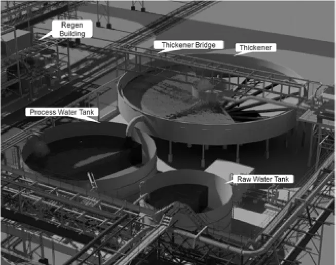
图1 浓缩器基本结构
目前工业生产中所应用的主流浓缩器大约有四种类型.[20-35]
1.1 圆形池浓缩器
圆形池浓缩器[7]:圆形池浓缩器直径小于200 m,一般被应用于大规模浓缩过程以及浓度相对较低的悬浮液中的固体分离过程(图2).

图2 圆形浓缩器
1.2 圆形高容量浓缩器
圆形高容量浓缩器[7]:圆形高容量浓缩器,其直径介于4 m至18 m之间.这种类型的浓缩器通常被采用于分离快速沉淀固体的过程中,而且圆形高容量浓缩器在此过程中又能够保证足够充分的灵活使用空间(图3).
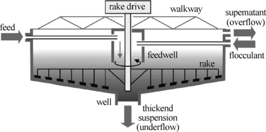
图3 圆形高容量浓缩器
1.3 深锥浓缩器
深锥浓缩器[7]:这种浓缩器与传统的浓缩器有着相似的外部形态,其典型直径最大为15 m.因此,此款浓缩器更适用于较小规模的生产应用过程(图4).

图4 深锥浓缩器
1.4 薄板浓缩器
薄板浓缩器[7]:薄板浓缩器是另外一种常用的工业沉淀设备,但是其外形结构与其他的主流浓缩器有着很大的不同(图5).这种浓缩器的典型直径为26 m.

图5 薄板浓缩器
2 实 例
本文以一个工程实例,介绍并分析了一个工业用浓缩器的基本尺寸选择及参数计算的方法.通过对工业用浓缩器发展的分析,以及对其不同运行模式和基本设计方法的研究.发现根据不同种类待处理液中固体的含量以及固体颗粒大小,可计算得出所完成此浓缩过程所需要的沉淀时间,进而可计算出浓缩器所需要的直径尺寸,从而能够更准确的设计和选择适合这一浓缩过程的浓缩器设备(详见英文稿).
3 结 语
虽然有着较大的空间及较长的运行时间需要,但相对于成本及维护费用高,产能较低的膜分离技术,工业用浓缩器的高产能,低成本,低耗能和结构简单等优势,会使其一直保持着自己在工业领域不可被取代的地位,并向着一个更有针对性,更高效节能环保的方向发展.
[1] American Institute of Mining.Transactions of the American Institute of Mining,Metallurgical,and Petroleum Engineers[J].University of California,1915,49:219.
[2] Alban J Lynch,Chester A Rowland.The history of grinding[M].Littleton,Colorado,USA:SME,2005:22.
[3] Arthur L Kohl,Richard B Nielsen.Gas purification(Fifth Edition)[M].S A:Elsevier Inc,1997:810812.
[4] Coe H S,Clevenger G H.Transactions[J].American Institute of Mining Engineers,1916,55(9):356386.
[5] Comings E W.Continuous Settling and Thickening[J].Ind Eng Chem,1954,48(8):11641165.
[6] Dr C Poole.Particle Process Engineering Handout[M].Leeds:University of Leeds,2010.
[7] Tarleton E S,Wakeman RJ.Solid/liquid separation:equipment selection and process design[M].Oxford:Butterworth-Heinemann,2007:611.
[8] Fitch B.Sedimentation of flocculent suspensions:sate of the art[J].A I Ch E J,1979,25:913930.
[9] Fitch B.Kynch theory and compression zones[J].A I Ch E J,1983,29:940947.
[10] Font R.Compression zone effect in batch sedimentation[J].A I Ch E J,1988,34:229238.
[11] Font R.Calculation of the compression zone height in continuous thickener[J].A I Ch E J,1990,36:312.
[12] Forbes D L H.The settling of mill slimes[J].Engineering and Mining Journal,1912,93:411415.
[13] Great Basin Gold,Gold Stocks Daily,30thAugust,c2010.Also available[online].[Accessed 19thNovember 2010][EB/OL].Available from World Wide Web:<http://goldstocksdaily.com/2010/08/30/great-basin-gold/>.
[14] Hassett N J.Design and operation of continuous thickeners[J].Ind Chemist,1958,34:116120,169172,489494.
[15] Nichols H G.Method of Settling Slimes,Transactions of the International Engineering Congress[J].American Society of Civil Engineer,1908,17.
[16] Farrow J B,Fawell P D,Johnston R R M,et al.Swift.Recent developments in techniques and methodologies for improving thickener performance[J].Chemical Engineering Journal,2000,80:149155.
[17] Kos P.Gravity thickening of water treatment plant sludges[B].J AWWA,1977:272283.
[18] Kynch G J.A theory of sedimentation[J].Trans Faraday Soc,1952,48:165177.
[19] Ladislav Svarovsky.Solid-liquid separation[M].4thedition Oxford,Boston:Butterworth-Heinemann,2000:15.
[20] María Cristina Bustos. Sedimentation and thickening:phenomenological foundation and mathematical theory[M].Netherlands:Kluwer Academic Publishers,1999:46.
[21] Rudman M,Paterson D A,Simic K.Efficiency of raking in gravity thickeners[J].International Journal of Mineral Processing,2010,95:3039.
[22] Burger R,Karlsen K H,Klingenberg C,et al.A front tracking approach to a model of continuous sedimentation in ideal clarier–thickener units[J].Nonlinear Analysis:Real World Applications,2003(4):457481.
[23] Richard J,Wakeman E S.Tarleton.Solid/liquid separation:scale-up of industrial equipment[M].Oxford:Elsevier Ltd,2005:21.
[24] Richardson J F.Chemical engineering.Volume 2,Particle technology and separation processes[M].Amsterdam,Boston:Butterworth-Heinemann,2007:256.
[25] Robert H Perry,Don W Green.Perry's chemical engineers'handbook(8th Edition)[M].New York:McGraw-Hill,2008:6975.
[26] JOHNSTON R R M,SIMIC K.IMPROVING THICKENER OPERATION AND CONTROL BY MEANS OF A VALIDATED MODEL[J].Minerals Engineering,1991,4(7-11):695705.
[27] Mishler R T.Settling Slimes at the Tigre Mill[J].Engineering and Mining Journal,1912,94:643.
[28] Scott K J.Theory of thickening:factors affecting settling rate of solids in flocculated pulps[J].Trans Inst Min Met,1968,77:8598.
[29] Stewart R F,Roberts E J.The sedimentation of the motion of pendulums[J].Trans Cambridge Phil,Soc,1851,9(2):8106.
[30] Talmadge W P,Fitch E B.Determining thickener unit areas[J].Ind Engng Chem,1955,47:3841.
[31] Telles A.The concept of superficial porosity and its implications on flow through porous media[M].Brazil:Universidade Federal de Rio de Janeiro,Report COPPE,1977.
[32] Tiller F.Revision of Kynch sedimentation theory[J].A I Ch E Journal,1981,27:822830.
[33] Thacker W C,Lavelle J W.Two-phase flow analysis of hindered settling[J].Phys Fluids,1977,20:15761579.
[34] Thacker W C,Lavelle J W.Stability of settling of suspended sediments[J].Phys Fluids,1978,21(2):291293.
[35] Tory E M,Hesse C H.Theoretical and experimental evidence for a Markov model for sedimentation,in Sedimentation of Small Particles in a Viscous Fluid[M].Southampton:Computational Mechanics Publications,1996:241281.
0 Introduction
Nowadays,in the process of practical industrial production procedure,particle process technology undertakes essential function in dealing with various kinds of materials’particle.Above all,as a significant part of the particle process in the mineral industry and chemical industry,sedimentation process acts as the role of rough separation.Within the whole process,it separates the mixture fluid into solid and liquid individually.Normally,there have three different methods can be used to achieve the sedimentation process.First of all,it is gravity sedimentation.The second method is centrifugal acceleration sedimentation or centrifugal sedimentation.And the third one is electromagnetic sedimentation by using the electromagnetism as a sedimentation force resource.Furthermore,considering about the gravity sedimentation,the available gravity sedimentation equipment can be divided into batch operated settling tanks and continuously operated thickeners or clarifiers[1-19].
As one of these three most basic and widely applied equipments,thickener is representing a class of typical solid-walled separator,shown in the figure 1.This set uses gravitational forces to raise the concentration of a suspension through sedimentation to produce thickened sludge with clear liquid overflow.

Fig.1 Photograph of a basin thickener installation[13]
Based on thickeners’scale and the treating methods,they can be divided into several types.Such as,circular basin thickener,circular high capacity thickener,deep cone thickener,lagoon thickener,lamella thickener and setting tank thickener.And more intensively,there has an report pointed out that the normal size of a circular basin thickener is less than 200 m in diameter,circular high capacity thickener is between 4 m and 18 m,deep cone thickener’s diameter is up to 15 m,lamella thickener is equal to 26 m in diameter[7].In addition,the mixtures which feed into the thickener always have different properties such as the particle size,viscosity,concentration,temperature and density.And the thickener types can be changed varying with the different application conditions.Therefore,to determine the selection and design of the suitable thickener,it is necessary to consider the significant factors.For instance,the mixtures’different particle size and the requirements of the properties of after treated material.Within the discussion content,some introduction with regard to the thickeners’selection and design concepts,methods and calculations will be presented.
1 Thickeners’development history
The first continuous thickener was invented by John Van Nostrand Dorr in 1906,at that time Dorr was engaged by the Mogul Mining Co.to change the Kildonan mill at Pluma,SD,from a 100-ton dry cyanide plant into a 300-ton wet-crushing mill following the practice at the Lund-berg[1].The Dorr thickener was the first continuous sedimentation unit in which water could be removed from dilute slurry and the solids concentrated into dense slurry.The continuous thickener allowed water to be recycled from the mill tailings pond to points within the mill circuit,greatly reducing the volume of fresh water that had to be used in the mill[2].After Dorr’s innovation,thickener gradually became essential in many industrial processes,such as mining,water treatment,food industry and so on.Meanwhile,this innovation itself was kept on improving by world’s scientists as shown in table 1[1-35].2 Operation methods and basic structure of thickener
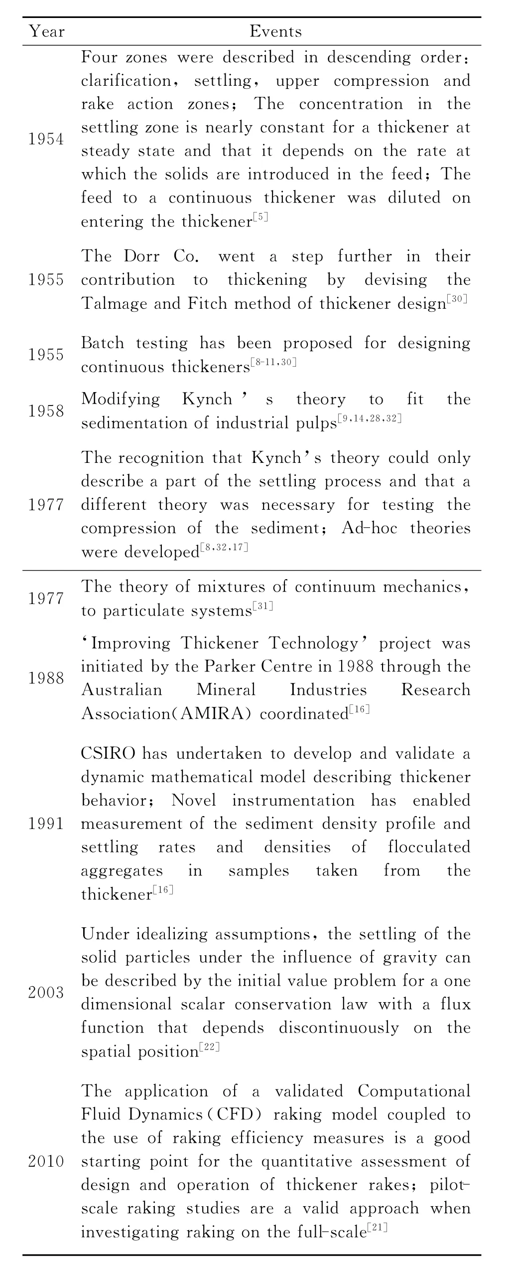
Year Events 1954 Four zones were described in descending order:clarification,settling,upper compression and rake action zones;The concentration in the settling zone is nearly constant for a thickener at steady state and that it depends on the rate at which the solids are introduced in the feed;The feed to a continuous thickener was diluted on entering the thickener[5]1955 The Dorr Co.went a step further in their contribution to thickening by devising the Talmage and Fitch method of thickener design[30]1955 Batch testing has been proposed for designing continuous thickeners[8-11,30]1958 Modifying Kynch’s theory to fit the sedimentation of industrial pulps[9,14,28,32]1977 The recognition that Kynch’s theory could only describe a part of the settling process and that a different theory was necessary for testing the compression of the sediment;Ad-hoc theories were developed[8,32,17]1977 The theory of mixtures of continuum mechanics,to particulate systems[31]1988‘Improving Thickener Technology’project was initiated by the Parker Centre in 1988 through the Australian Mineral Industries Research Association(AMIRA)coordinated[16]1991 CSIRO has undertaken to develop and validate a dynamic mathematical model describing thickener behavior;Novel instrumentation has enabled measurement of the sediment density profile and settling rates and densities of flocculated aggregates in samples taken from the thickener[16]2003 Under idealizing assumptions,the settling of the solid particles under the influence of gravity can be described by the initial value problem for a one dimensional scalar conservation law with a flux function that depends discontinuously on the spatial position[22]2010 The application of a validated Computational Fluid Dynamics(CFD)raking model coupled to the use of raking efficiency measures is a good starting point for the quantitative assessment of design and operation of thickener rakes;pilotscale raking studies are a valid approach when investigating raking on the full-scale[21]
With the consideration of thickener’s operation method,it illustrates that thickener is an industry unit from which the concentration of a suspension can be increased by the sedimentation process,and with a clear liquid formation.However,the concentration of the suspension is high and it resists the settling takes place.Normally,thickeners operate as continuous or batch units in the treatment process,and consist of tanks from which the clear liquid is taken off at the top of it and the thickened sludge or liquor is taken off at the bottom.For example,the operation method of continuous thickener is briefly shown by the Figure 2 below.

Fig.2 Flow in continuous thickener[24]
Based on a given size,in order to obtain the greatest possibility through putting from the thickener,the sedimentation rate should be as high as possible.In the practical process,for the purpose of increasing the sedimentation rate,artificially add a small quantity of an electrolyte is a widespread and basic method.As the result,this method will lead to the formation of flocs and precipitation of colloidal particles.Furthermore,with the terms of reason that the function of lowers the viscosity of the liquid,and encourages the larger one of the particles in the suspension to grow in size at the expense of the more soluble small particles,the suspension is also frequently heated.On the other hand the thickener always incorporates a slow stirrer.The stirrer normally locates on the bottom of the cylinder,and it causes a reduction in the apparent viscosity of the suspension.Meanwhile,the stirrer in the tank also aids in the in the consolidation of the sediment.In addition,two major style thickeners,batch thickener and continuous thickener have difference on their basic structure.The batch thickener usually consists of a cylindrical tank with a slightly conical bottom.Through adequate time sedimentation,the thickened liquor is withdrawn from the bottom as the sludge and the clear liquid discharged by an adjustable off-take tube from the top side of the cylinder.And with regard the continuous thickener,it frequently consists of a cylindrical tank with a flat bottom.Its suspension has been fed in below the surface with 0.3 to 1 m depth at the centre of the tank.The liquor of the processed mixture is continuously discharge by an outlet at the bottom of the tank,and any solids which are sediment on the lower side of the tank may be directed throughout the outlet by means of a slowly rotating scraper[24].
3 Basic design and selection of thickeners
In order to select a perfect match thickener that would be applied within the desirable treatment process.It is essential to learn about the properties of varies kinds of mixtures liquid sufficiently.The table 2 below lists several mixtures liquid and their main characteristics.
On the other hand,through the above varies mixture,there is no denying that to choose the suitable thickener is a necessary step in practical industry sedimentation process.Based on the above representation which regard to method and structure section,normally,there have two major types of thickener,one is bath thickener and the other is continuous.With an intensive research,the references illustrate that the major thickeners can be divided into more segmentation styles,such as circular basin thickener,circular high capacity thickener,deep cone thickener,lagoon thickener,lamella thickener,setting tank thickener etc.
Firstly,circular basin thickeners(diameter less than 200 m)have been always applied in larger scale thickening and separating of solids from relatively dilute suspension.And it has three operation zones:clarification,zone settling,and compression.The settler diameter and the settler depth are the function of the solution circulation rate,which is determined by the required production rate;and the function of the compression-zone retention time needs to obtain the require underflow concentration[3].Moreover,the typical particle size and feed concentration range for circular basin thickener are 0.1-500μm and<20%w/w,it comprises arelatively shallow,open-top cylinder with either a flat bottom or a bottom shaped in the form of an inverted cone[7](see Figures 3 below).

Table 2 Estimating design data for areas of application[6]
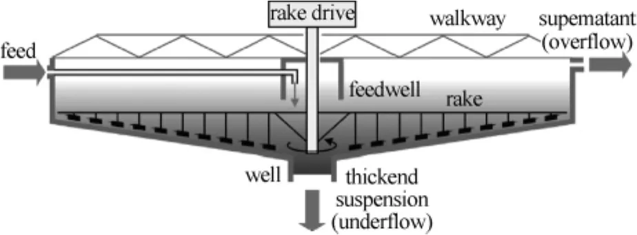
Fig.3 Circular basin thickener[7]
Secondly,regarding the circular high capacity thickeners(diameter is between 4 m and 18 m).This kind of thickener is usually used in the process of separating the rapid settling solids,and the available space is at a premium.And 0.1-300μm and<15%w/w are the normally particle size and feed concentration range of the circular high capacity thickeners.The circular high capacity thickener is mostly as the same as a conventional circular basin thickener in the general form(see Figure 4.Below),except the diameter and the material of the tank’s wall.

Fig.4 Circular high capacity thickeners[7]
Circular basin thickener’s wall is made of combination of concrete and steel.Nevertheless,high capacity thickener’s wall is only made of steel.Although,in this kind of thickener,large flocs that sediment very quickly can be generated to allow thickeners with high solids handling capacities and relatively small floor areas to be produced[7].On the contrary,the flocculant usage is notably higher.Hence,it will be more expensive to operate a circular high capacity thickener.
For the next one is the deep cone thickener,shown in the Figure 5 below.Again the form is similar to the conventional thickener.The diameter of this thickener is up to 15 m,thus it is suitable for small scale operation.Furthermore,the typical particle size and feed concentration range are 0.1-300μm and<15%w/w[7].For researching the advantages and disadvantages about this thickener,it is simply can find that the deep cone thickener is occupy a small place and cheap to install,but the operation and efficient settling flocculants are generally expensive.And it always needs high power to support the system to maintain the stirring action when it deals with the high viscosity underflows.
Last but not least,lamella thickener is another style of common sedimentation equipment.Basically,lamella thickener’s size is equal to 26 m in diameter.And its typical particle size and feed concentration range are 1–150μm and<15%w/w(see Figure 6 below)[7].
The general form of lamella thickener is an essentially rectangular tank that containing a series of closely spaced rectangular plates inclined at an angle of about 500 to the tank’s lower face.This structure is design to increase the available settling area efficiently,and this will raise the sedimentation rate by allowing the sedimenting solids from the feed to slide down their upper surfaces towards a sludge hopper.However,the disadvantage of lamella thickener is also obviously existed.Especially,maintaining the equipment is not convenience because of the complex structure.

Fig.5 Deep cone thickener[7]

Fig.6 Lamella thickener[7]
Meanwhile,the suitable selection and design of thickener must base on the comprehensive calculation.For a practical example,design a suitable safe working diameter for a thickener that required producing an underflow with the concentration of 50%solid by weight and the rate of feed is 80 ton/hr.And the safety factor here is 1.5,the solids special gravity is 2 and the feed is 200 g solids per litre pulp.Moreover,calculation should base on the batch settling test result table and graph below(Figure 7)[6].
Solution(method is the similar as in the handout):Because feed pulp contains 200 g solids.Thus,initial dilution

And the required of V/F concentration is 50%by weight.Hence,1 kg pulp would include 500 g solids+500 g water.
Moreover,the volume of 500 g solids is
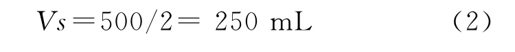

Fig.7 Batch settling test results mudline height change
So,the total volume occupied by 1 kg pulp is

The above calculation example is a rough and basic design method.For the purpose of designing the thickener all-sided,other factors should also be considered when complete the design procedures.For instance,in the determination of thickener basin area,the area requirement for each solid concentration tested is calculated by relating the net overflow rate to the corresponding interfacial settling rate.It illustrated by the equation below:

Where Ciis the solids concentration at the interfacial settling velocity vi.
Cuis the underflow concentration.Both Ciand Cubeing expressed in terms of mass of solids per unit volume of slurry.
Furthermore,in the lamella thickener the simulation method,which should be considered in the effective area calculation,is different.The total project area of lamella thickener for separation is equal to the sum of project area or all channels on the horizontal plane. The horizontally project area Ascan be calculated as:

L is the settling length;W is the plane width;αis the plane inclining angle[25].
Using the methods and equations above,the table of the thickener selection can be obtained(Table 3 below)[23].From this table in different situations the suitable type of thickener has been indicated clearly,and the table itself is easy to apply in practical.
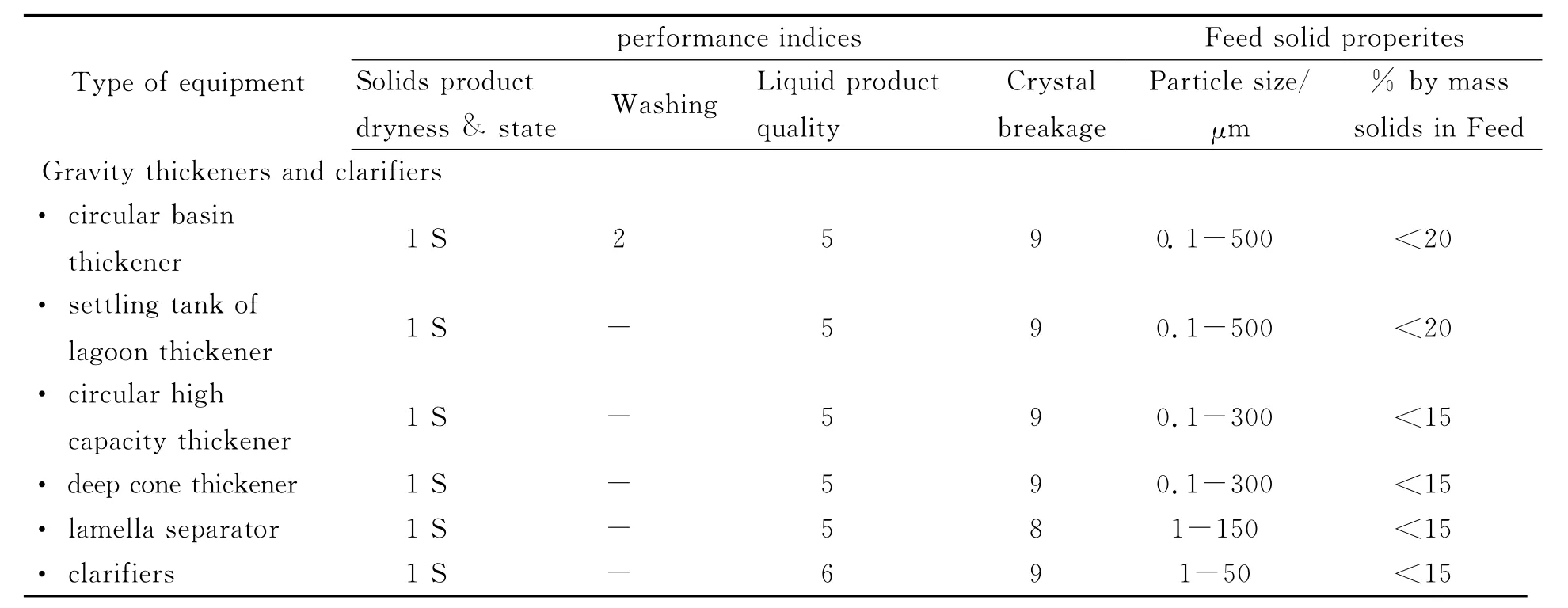
Table 3 Thickener selection
4 Conclusion
To sum up,the above representation content has particularly introduced the four major thickeners which have already been applied in the industrial processes and also described the researching history of developments in techniques and methodologies for improving thickener performance.At the same time,based on the massive research data,a significant and crucial analysis with regard to the gravity sedimentation thickeners’advantages and disadvantages has been obtained.Obviously,because of the space and operating time they need,the gravity sedimentation thickeners are more suitable for large scale and long period operation.However,compared with the membrane separation technique,the gravity sedimentation thickener has the lowest construction and maintains cost,simplest structure,and large output.Furthermore,for the purpose of accurate design,the feed solid properties such as particle size,percentage of solid in the feed,viscosity should be determined by using the relevant equipments and considered as important factors in the thickener’s design.Simultaneously,the suitable selection and design of thickener must base on the comprehensive calculation.Using equations(1),(4),(6),(8)and(10)to obtain the thickener’s unit area,then combining with equations(12),(13)and other factors’defined equations to get the accurate size and suitable structure selection of the thickener.
Finally,through the process of dealing with different industrial mixtures by using different operation methods,the significant part is that in order to design and screen out the most appropriate thickener to meet the application requirement,the factors such as different mixtures’properties,different thickeners’operation methods and different designed calculation equations all of these will be took into account.In a word,thickeners will develop to a more efficient and selective direction.
[1] American Institute of Mining.Transactions of the American Institute of Mining,Metallurgical,and Petroleum Engineers[J].University of California, 1915,49:219.
[2] Alban J Lynch,Chester A Rowland.The history of grinding[M].Littleton,Colorado,USA:SME,2005:22.
[3] Arthur L Kohl,Richard B Nielsen.Gas purification(Fifth Edition)[M].S A:Elsevier Inc,1997:810812.
[4] Coe H S,Clevenger G H.Transactions[J].American Institute of Mining Engineers,1916,55(9):356386.
[5] Comings E W.Continuous Settling and Thickening[J].Ind Eng Chem,1954,48(8):11641165.
[6] Dr C Poole.Particle Process Engineering Handout[M].Leeds:University of Leeds,2010.
[7] Tarleton E S,Wakeman RJ.Solid/liquid separation:equipment selection and process design[M].Oxford:Butterworth-Heinemann,2007:611.
[8] Fitch B.Sedimentation of flocculent suspensions:sate of the art[J].A I Ch E J,1979,25:913930.
[9] Fitch B.Kynch theory and compression zones[J].A I Ch E J,1983,29:940947.
[10] Font R.Compression zone effect in batch sedimentation[J].A I Ch E J,1988,34:229238.
[11] Font R.Calculation of the compression zone height in continuous thickener[J].A I Ch E J,1990,36:312.
[12] Forbes D L H.The settling of mill slimes[J].Engineering and Mining Journal,1912,93:411415.
[13] Great Basin Gold,Gold Stocks Daily,30thAugust,c2010.Also available[online].[Accessed 19thNovember 2010][EB/OL].Available from World Wide Web:<http://goldstocksdaily.com/2010/08/30/great-basin-gold/>.
[14] Hassett N J.Design and operation of continuous thickeners[J].Ind Chemist,1958,34:116120,169172,489494.
[15] Nichols H G.Method of Settling Slimes,Transactions of the International Engineering Congress[J].American Society of Civil Engineer,1908,17.
[16] Farrow J B,Fawell P D,Johnston R R M,et al.Swift.Recent developments in techniques and methodologies for improving thickener performance[J].Chemical Engineering Journal,2000,80:149155.
[17] Kos P.Gravity thickening of water treatment plant sludges[B].J AWWA,1977:272283.
[18] Kynch G J.A theory of sedimentation[J].Trans Faraday Soc,1952,48:165177.
[19] Ladislav Svarovsky.Solid-liquid separation[M].4thedition Oxford,Boston:Butterworth-Heinemann,2000:15.
[20] María Cristina Bustos. Sedimentation and thickening:phenomenological foundation and mathematical theory[M].Netherlands:Kluwer Academic Publishers,1999:46.
[21] Rudman M,Paterson D A,Simic K.Efficiency of raking in gravity thickeners[J].International Journal of Mineral Processing,2010,95:3039.
[22] Burger R,Karlsen K H,Klingenberg C,et al.A front tracking approach to a model of continuous sedimentation in ideal clarier–thickener units,Nonlinear Analysis:Real World Applications,.2003(4):457481.
[23] Richard J,Wakeman E S.Tarleton.Solid/liquid separation:scale-up of industrial equipment[M].Oxford:Elsevier Ltd,2005:21.
[24] Richardson J F.Chemical engineering.Volume 2,Particle technology and separation processes[M].Amsterdam,Boston:Butterworth-Heinemann,2007:256.
[25] Robert H Perry,Don W Green.Perry's chemical engineers'handbook(8th Edition)[M].New York:McGraw-Hill,2008:6975.
[26] JOHNSTON R R M,SIMIC K.IMPROVING THICKENER OPERATION AND CONTROL BY MEANS OF A VALIDATED MODEL[J].Minerals Engineering,1991,4(7-11):695705.
[27] Mishler R T.Settling Slimes at the Tigre Mill[J].Engineering and Mining Journal,1912,94:643.
[28] Scott K J.Theory of thickening:factors affecting settling rate of solids in flocculated pulps[J].Trans Inst Min Met,1968,77:8598.
[29] Stewart R F,Roberts E J.The sedimentation of the motion of pendulums[J].Trans Cambridge Phil,Soc,1851,9(2):8106.
[30] Talmadge W P,Fitch E B.Determining thickener unit areas[J].Ind Engng Chem,1955,47:3841.
[31] Telles A.The concept of superficial porosity and its implications on flow through porous media[M].Brazil:Universidade Federal de Rio de Janeiro,Report COPPE,1977.
[32] Tiller F.Revision of Kynch sedimentation theory[J].A I Ch E Journal,1981,27:822830.
[33] Thacker W C,Lavelle J W.Two-phase flow analysis of hindered settling[J].Phys Fluids,1977,20:15761579.
[34] Thacker W C,Lavelle J W.Stability of settling of suspended sediments[J].Phys Fluids,1978,21(2):291293.
[35] Tory E M,Hesse C H.Theoretical and experimental evidence for a Markov model for sedimentation,in Sedimentation of Small Particles in a Viscous Fluid[M].Southampton:Computational Mechanics Publications,1996:241281.
Review on development and their basic design of thickeners
ZHANG Zhaoxi
(Chemical Engineering,University College of London,Gower Street,London WCIE 6BT)
Based on the research discovery,it is obvious that sedimentation process undertakes an important role in both domestic application and industrial production procedure.And thickener is a typical equipment of this process.It has been applied in several aspects such as water treatment,chemical industry,pharmaceutical industry and mineral industry etc.This paper reviews the relevant literature and the different types and basic operation methods of thickeners.Moreover,the representative calculation methods which involve the design and selection of suitable thickener will be discussed.
sedimentation;thickeners;calculation method;design
文章编号:16742869(2011)10003507
TQ051
A
10.3969/j.issn.1674-2869.2011.10.009
16742869(2011)10003203
20110908
张兆熙(1988),湖北武汉人,硕士研究生.研究方向:化学工程过程.
龚晓宁
猜你喜欢
节能与环保(2022年3期)2022-04-26 14:32:50
数学物理学报(2021年3期)2021-07-19 06:02:36
重型机械(2020年2期)2020-07-24 08:16:12
电气技术(2016年6期)2016-10-15 06:06:17
焊接(2016年5期)2016-02-27 13:04:42
焊接(2015年10期)2015-07-18 11:04:46
能源(2015年8期)2015-05-26 09:15:50
能源(2015年8期)2015-05-26 09:15:48
中国当代医药(2015年10期)2015-03-01 02:02:30
分析测试学报(2015年10期)2015-02-28 16:40:56
