Numerical Simulation of Viscoelastic Extrudate Swell ThroughElliptical Ring Die*
XU Xingming (许星明), ZHAO Guoqun (赵国群), QIN Shengxue (秦升学) and WANG Wei (王威)
Numerical Simulation of Viscoelastic Extrudate Swell ThroughElliptical Ring Die*
XU Xingming (许星明)1,2, ZHAO Guoqun (赵国群)2,**, QIN Shengxue (秦升学)3and WANG Wei (王威)1
1College of Mechanical and Electrical Engineering, Shandong University of Science and Technology, Tai’an 271019, China2Engineering Research Center for Mold & Die Technologies, Shandong University, Jinan 250061, China3College of Mechanical and Electrical Engineering, Shandong University of Science and Technology, Qingdao 266510, China
The numerical simulation of extrudate swell is significant in extrusion processing. Precise prediction of extrudate swell is propitious to the control of melt flow and the quality of final products. A mathematical model of three-dimensional (3D) viscoelastic flow through elliptical ring die for polymer extrusion was investigated. The penalty function formulation of viscoelastic incompressible fluid was introduced to the finite element model to analyze 3D extrusion problem. The discrete elastic viscous split stress (DEVSS) and streamline-upwind Petrov- Galerkin (SUPG) technology were used to obtain stable simulation results. Free surface was updated by updating the streamlines which needs less memory space. According to numerical simulation results, the effect of zero-shear viscosity and elongation parameter on extrudate swell was slight, but with the increase of volumetric flow rate and relax time the extrudate swell ratio increased markedly. Finally, the numerical simulation of extrudate swell flow for low-density polyethylene (LDPE) melts was investigated and the results agreed well with others’ work. These conclusions provided quantitative basis for the forecasting extrudate swell ratio and the controlling of extrusion productivity shape.
viscoelastic fluid, extrudate swell, finite element method, polymer extrusion
1 INTRODUCTION
Extrudate swell is a common elastic manifestation existed in polymer processing, which is also known as die swell. The prediction of extrudate swell ratio is of great significance in both theoretical and industrial context[1, 2]. The selection of appropriate numerical scheme has great influence on accurate simulation of flow properties and flow patterns [3]. Much effort has been made in attempting to find robust and stable numerical methods including finite difference method [4, 5], finite volume method [6], finite element method [7], spectral method [8], and boundary integral method [9]. Among them, the finite element method incarnates the advantage of adaptability to the complex geometry boundaries [10].
Based on the numerical simulation methods mentioned above, many researchers have investigated the extrudate swell behavior with different rheological models. Mitsoulis and Heng simulated die swell ratio of Newtonian liquids for diverging, straight and converging dies respectively [11]. They found out that for all resins examined, the diameter swell ratio of converging dies is always higher than that of the diverging dies. Garcia-Rejon. did further research on extrudate swell ratio for diverging and converging dies [12]. They found that thickness extrudate swell ratio increases with the increase of die contraction ratio but decreases with the increase of inclination angle and the length of tapered section. They also compared the extrudate swell ratio of Newtonian liquids with that of non-Newtonian liquids. Mitsoulis worked on extrudate swell ratio of pseudoplastic and viscoplastic fluids [13], and came to the conclusion that the thickness swell ratio increases monotonically as shear-thickening increases, extreme shear-thinning produces no swelling and no exit correction for power law liquids, while for the viscoplastic Bingham model, the thickness swell ratio decreases to zero as viscoplasticity increases. Ganvir. proposed a method for the numerical simulation of extrudate swell ratio using an Arbitrary Lagrangian Eulerian (ALE) technique based finite element formulation [14]. They predicted die swell ratio of planar and axisymmetric extrusion with abrupt contraction ahead of the die exit.
In actual manufacture, precise geometric dimension is essential to produce qualified final products and die swell is considered one of the primary obstacles in product shape control [15]. As is known to all, when the melt flows out of the die orifice, the melt extends to all directions when die swell happens. However, most of the relevant numerical simulation work done before mainly aimed at two-dimensional or axisymmetric flow problems and most of the cross sectional shape is simply circular, annular or rectangular. The full 3D simulation is necessary to obtain more realistic flow properties and patterns. In the present work, we established the mathematical model of 3D polymer die swell of elliptical ring die with differential constitutive equation. Free surface was updated with decoupled method by updating the streamlines which needs less memory space than Gandharv Bhatara’s method adopted by Guo[16]. The numerical simulation was executed with different material and technological parameters and the distribution of velocity, shear stress and first normal stress difference were analyzed.
2 MATHEMATIC MODELING
The flow of viscoelastic melt extrusion is typically governed by principles of conservation which are expressed in terms of partial differential equations [17].
Considering incompressible, isothermal and creeping steady flow, the governing equations of conservation of mass and momentum are simplified as follows:


whereis Cauchy stress tensor which is defined as

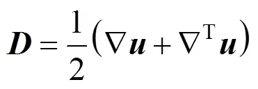
whereis strain rate tensor which is expressed as
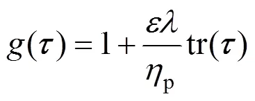
The Phan-Thien and Tanner (PTT) constitutive equation is adopted to describe the rheological characteristics of the polymer:


3 BOUNDARY CONDITIONS
To solve the above governing equations, it is necessary to impose appropriate boundary conditions. The boundary conditions are set as follows [20]:
(1) On the inlet boundary surface, the velocity is expressed as follows:


4 NUMERICAL PROCEDURE
4.1 Free surface update
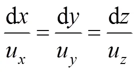
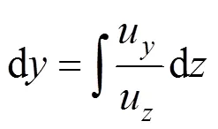
As the position of the free surface is unknown a priori, the surface update scheme turns out to be a challenge as it introduces non-linearity and the number of iteration increases to obtain a solution [21]. The free surface is found in a decoupled way. The contour of the free surface is first assumed, and then it is updated with the streamline equation [22]:
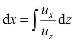
Integration in the-direction only, the new location of the free face is calculated from the velocity field based on the latest velocity field as follows [23]:
4.2 Finite element formulation
Considering both computational efficiency and memory requirement, the penalty finite element algorithm is introduced to solve the nonlinear governing equations [24]. By using the penalty model, the momentum Eq. (2) becomes:

The discrete elastic viscous split stress (DEVSS) method is adopted by introducing an additional elliptic term and then the momentum equation becomes [24]:

A Galerkin finite element discrete form is proposed by taking the same form of weighted function as that of interpretation function.

whereNis the isoparametric weighted function which is expressed as follows:

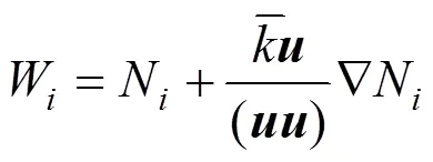

With the asymmetric weighted function adopted, the finite element formula of simplified Phan-Thien and Tanner (SPTT) model is obtained:

5 RESULTS AND DISCUSSION
5.1 Geometric model and simulation parameters
The geometry of the elliptic ring die is defined by the inner and outer ellipses (Fig. 1). The geometric parameters of computational domain is as follows: the length of longer axis of the outer ellipse1, the length of shorter axis of outer ellipse1, the length of longer axis of the inner ellipse2, the length of shorter axis of inner ellipse2, the entry length1and the extrudate length2. The origin of coordinates is set at the ellipse center of die outlet. Theaxis is along the flow direction,axis is along shorter axis of elliptical ring cross section andaxis is along longer axis of elliptical ring cross section. The values of geometric parameters and the values of material parameters for low-density polyethylene (LDPE) with the average molecular weight of 25000 are shown in Table 1 [16]. All the numerical simulation results below are calculated with the parameters in Table 1 unless otherwise specified.
The finite element meshes adopted in present paper are shown in Fig. 1. As the deformation of the melt around the die exit is relatively severe, the meshes near the die exit are refined. The coordinate direction is shown in the figure, and the origin of coordinate is set on the centre of die orifice. By taking both computational efficiency and calculation accuracy into consideration, only one quarter of the computational domain is used in the simulation due to symmetry.
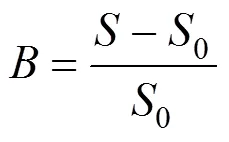
The swell ratio calculated by the finite element simulation is defined as
5.2 Mesh dependency
In order to study the effects of mesh refinements on the numerical results, four mesh division schemes are carried out as shown in Table 2. Fig. 2 shows the comparison of extrudate swell ratio respectively predicted with three meshes for the flow of PTT viscoelastic fluid. The material parameters are taken from Table 1. A similar distribution tendency of extrudate swell ratio is found from Fig. 2, whereas mesh 1 leads to a lower extrudate swell ratio and mesh 2 leads to a higher extrudate swell ratio. As the meshes reach to a certain number (mesh 3 and mesh 4), the extrudate swell ratio tends to be very much the same. Considering the sufficient accuracy and computational cost-effectiveness, mesh 3 is adopted as our base mesh and all the results to be given below are computed with the mesh 3 unless otherwise stated.

Table 2 Mesh characteristics

Table 1 Geometric and material parameters
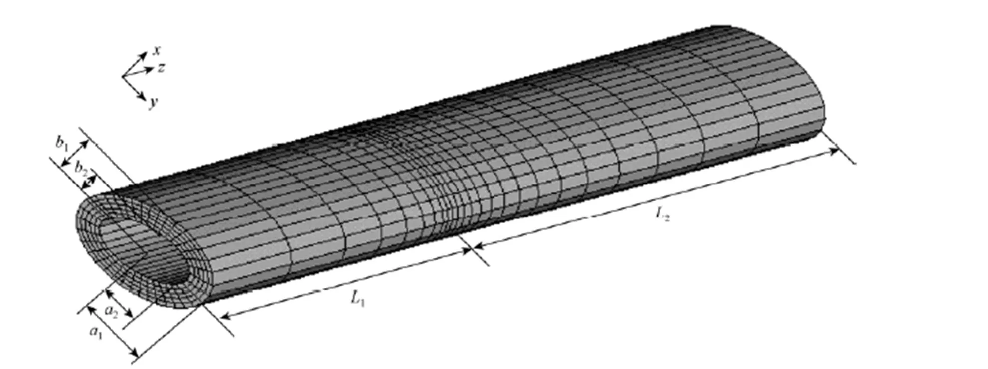
Figure 1 Finite element meshes used in the computation
Figure 2 Fitting curves of swell ratio-coordinate with different mesh numbers (Volumetric flow rate: 1.0×10⁻⁵m3·s-1; zero-shear viscosity: 1.0×10⁴Pa·s)
mesh number:□ 768;○ 1080; △ 1260; ▽ 1350
5.3 Distribution of physical quantities
5.3.1

5.3.2

5.3.3
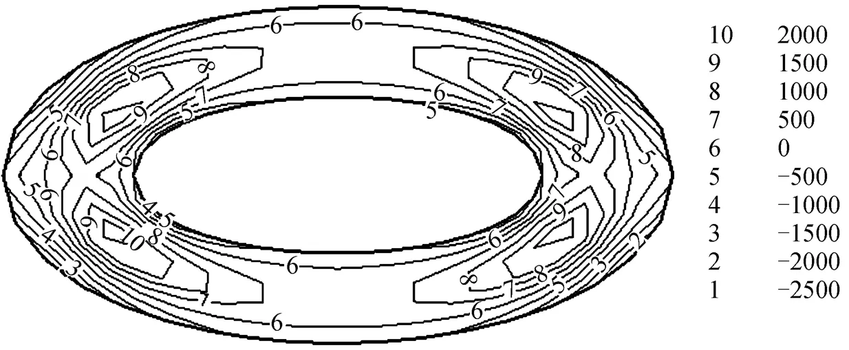
Normal stress difference is a characteristic parameter for polymer due to its elastic effect. Usually the value of first normal stress difference is much larger than that of second normal stress difference. Thus, the first normal stress difference is the main normal stress difference making the die swell occur. Fig. 6 shows the contours of first normal stress difference on different cross sections. Due to symmetry, only the right-hand side is drawn. Fig. 6 (a) shows the contours of first normal stress difference near to the die orifice on theplane, which suggest that the flow has already reached steady state inside the die, but the first normal stress difference changes greatly around the die orifice. When the deformation of the melt is restored outside the die, the first normal stress difference vanishes quickly. The contour of first normal stress difference near the die orifice on theplane is similar as shown in Fig. 6 (b), but the stress gradient around the die orifice is a little smaller.
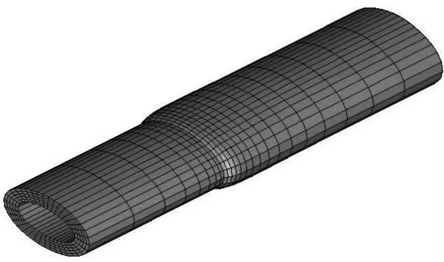
Figure 3 Deformed finite element meshes

(Volumetric flow rate: 1.0×10⁻⁵m3·s-1; zero-shear viscosity: 1.0×10⁴Pa·s)
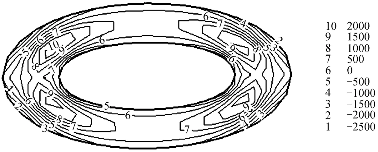

(Volumetric flow rate: 1.0×10⁻⁵m3·s-1; zero-shear viscosity: 1.0×10⁴Pa·s)
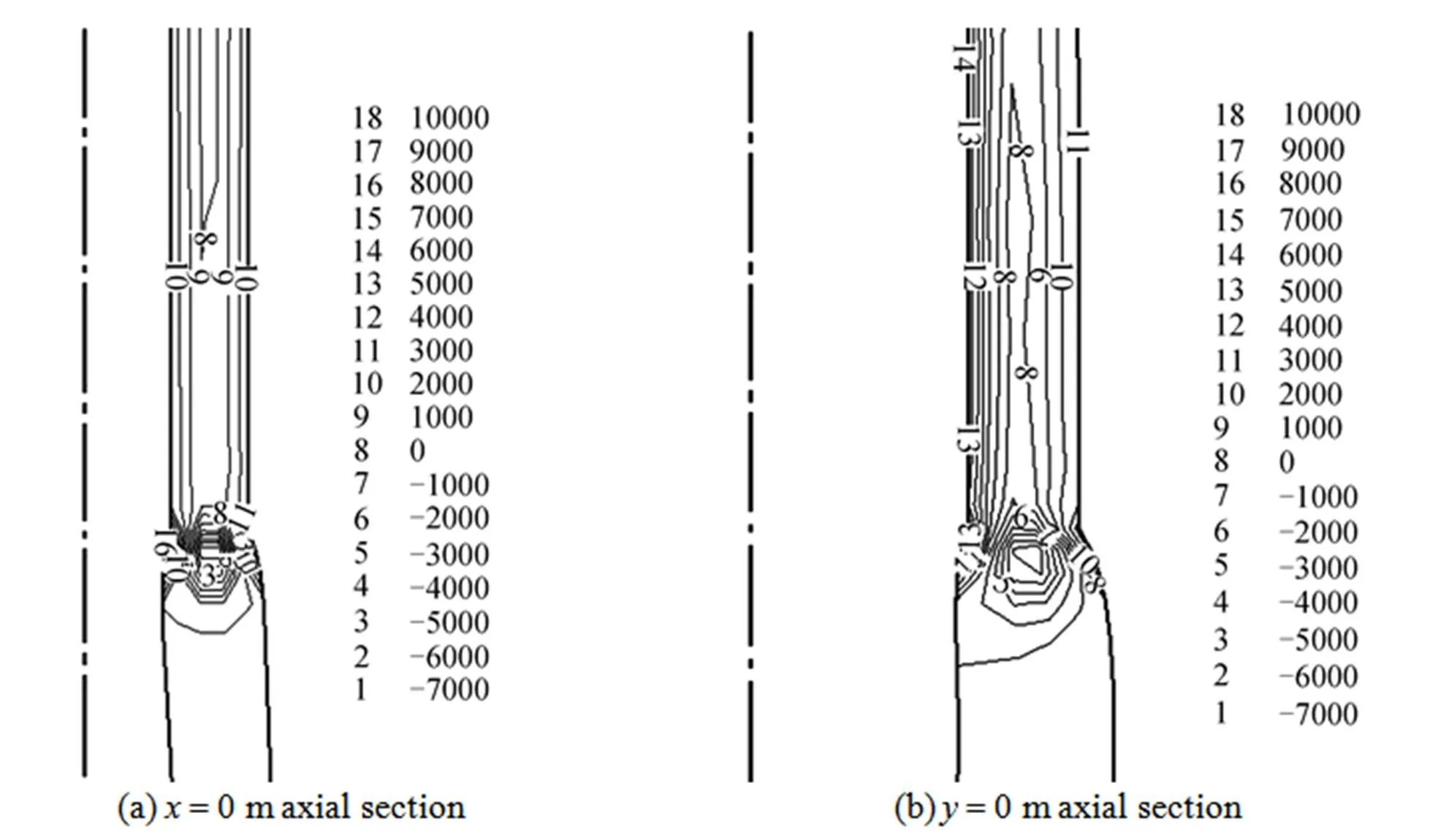
Figure 6 Contour of first normal stress difference (unit: Pa) on different cross sections
(Volumetric flow rate: 1.0×10⁻⁵m3·s-1; zero-shear viscosity: 1.0×10⁴Pa·s)
5.4 Effect of zero-shear viscosity
Viscosity is an important rheological parameter for polymers. As the solvent contributions to the total viscosity of the liquid are negligible, we set it to zero and the value ofpis equal to the zero-shear viscosity. Different zero-shear viscosities are selected in numerical simulation and we compare the extrudate swell ratio at the outlet surface, as shown in Fig. 7. The swell ratio decreases from 0.433 to 0.425 as the zero-shear viscosity increases from 10000 Pa·s to 50000 Pa·s, but the change of extrudate swell ratio is slight.
5.5 Effect of volumetric flow rate

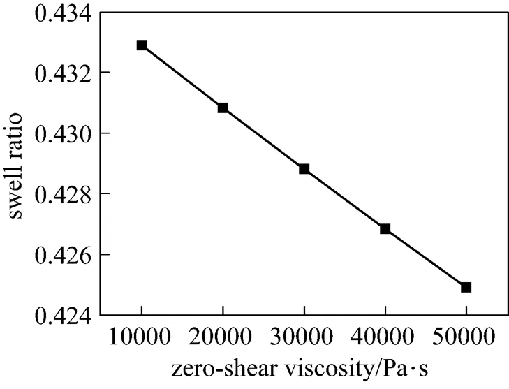
Figure 7 Effect of zero-shear viscosity on swell ratio
(Volumetric flow rate: 1.0×10⁻⁵m3·s-1)
(a) Volumetric flow rate of 1.0×10⁻⁵m3·s-1
(b) Volumetric flow rate of 3.0×10⁻⁵m3·s-1

(c) Volumetric flow rate of 5.0×10⁻⁵m3·s-1

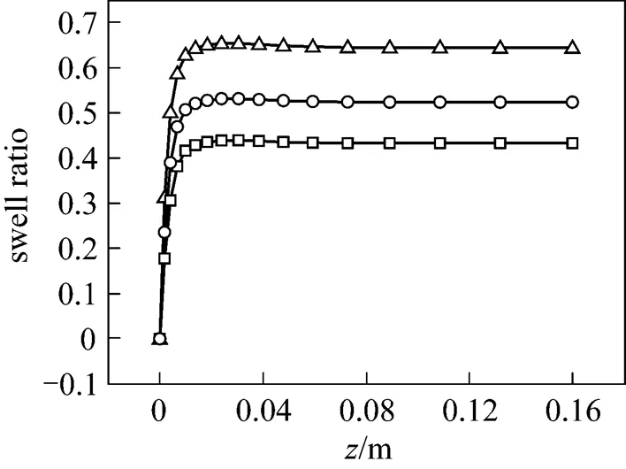
Figure 9 Effect of volumetric flow rate on swell ratio (Zero-shear viscosity: 1.0×10⁴Pa·s)
volumetric flow rate/m3·s-1:□ 1.0×10⁻⁵;○ 3.0×10⁻⁵;△ 5.0×10⁻⁵
5.6 Effect of relax time
From the stand point of rheology, relax time is a characteristic parameter that reflects elasticity of polymers. When relax time increases from 0.1 s to 1.0 s, the extrudate swell ratio at the outlet surface changes from 0.43 to 0.95, as shown in Fig. 10. It is known that relax time has much to do with polymer elasticity and the increase of relax time results in the increases of polymer elasticity.
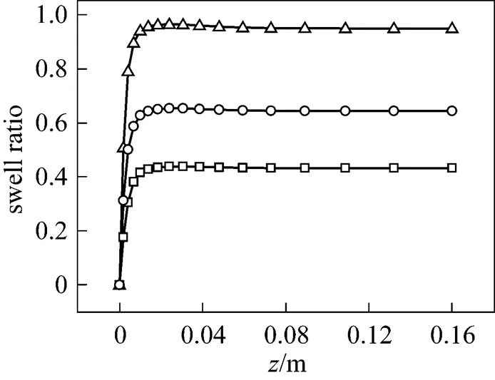
Figure 10 Fitting curves of swell ratio-coordinate with different relax times (volumetric flow rate: 1.0×10⁻⁵m3·s-1; zero-shear viscosity: 1.0×10⁴Pa·s)
relax time/s:□ 0.1;○ 0.5;△ 1.0
5.7 Effect of elongation parameter ε
The material parameterin PTT constitutive equation adopted in present paper controls elongation viscosity. Usually, elongation viscosity is 102-103times of shear viscosity. Shear viscosity is of shear thinning while the variation of elongation with shear rate is complex. As the parameterincreases, the extrudate swell ratio decreases, but the change is slight, as shown in Fig. 11. The variation of extrudate swell ratio withis similar with the variation of extrudate swell ratio with zero-shear viscosity.
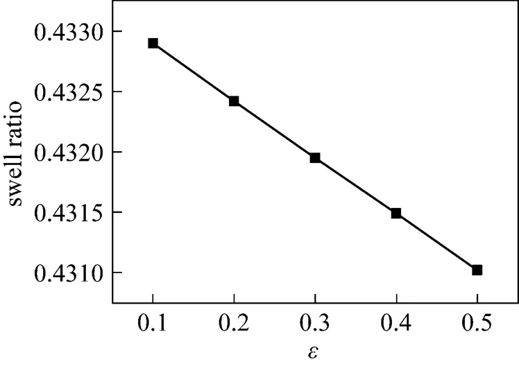
Figure 11 Effect ofon swell ratio
(volumetric flow rate: 1.0×10⁻⁵m3·s-1; zero-shear viscosity: 1.0×10⁴Pa·s)
5.8 Effect of the shape of die
Considering the effect of the die shape, annulus and elliptical ring dies with the same cross area are adopted to calculate extrudate swell ratio. It can be seen from Fig. 12 that the extrudate swell ratio of elliptical ring die is higher than that of annulus die taking the same parameters except for the geometry. For elliptical die, on the ends of longer axis the curvature is relatively big which goes against forming fully developed flow. Thus, more elastic deformation is produced inside the die and the extrudate swell ratio is higher as a result.
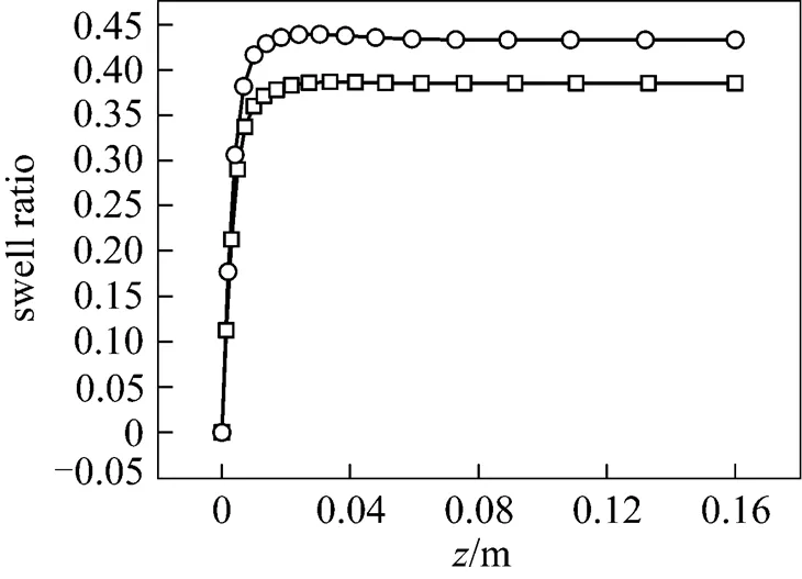
Figure 12 Effect of the shape of the die on swell ratio (volumetric flow rate: 1.0×10⁻⁵m3·s-1; zero-shear viscosity: 1.0×10⁴Pa·s)
die shape:□ annulus;○ elliptical ring
5.9 Comparison with other works
It is necessary to compare the results of our work with that of others. With the parameters taken by Huang. [27], extrudate swell simulation is executed with our computer code. As shown in Table 3, when the shearing rate is low, the simulation results obtained by Huang. were similar with their experimental results, but when the shearing rate is high, the deviation became obvious. It is considered that the wall slip was neglected at high shearing rate, which led to higher simulation results. The tendency of simulation results obtained in our work is the same as Huang’s simulation results. As the shearing rate increases, our simulation results are slightly lower than Huang’s.

Table 3 Comparison of swell ratio with other work [27]
6 CONCLUSIONS
In this study, a mathematical model of 3D viscoelastic flow through elliptical ring die for polymer extrusion swell was investigated. Location of free surface was updated with streamline equation in a decoupled method which is simpler and needs less memory space than Gandharv Bhatara’s method adopted by Guo. Numerical simulation was executed with different technological and material parameters. Extrudate swell ratio reduces with the increase of zero-shear viscosity and the material parameterin the PTT constitutive equation. But the influence of zero-shear viscosity andon extrudate swell ratio is slight. Higher volumetric flow rate leads to higher extrudate swell ratio. As the relax time increases, elasticity of polymers increases and higher extrudate swell ratio is obtained. At the same average flow rate, it is found that more elasticity deformation is generated in elliptical die than annulus die and the extrudate swell ratio is higher as a result. Finally, we compared our numerical results with that of others using the same parameters, and the results agreed well. The results show that the method for free surface update adopted was suitable to obtain accurate numerical result. And further more, calculation time was reduced as less memory space was needed.
In this paper, we only compared our numerical results with other’s experimental results due to the limitation of present experimental situation. In the future, more experiments will be carried out in succession to verify the feasibility and effectiveness of our numerical simulation method.
NOMENCLATURE
swell ratio
helement characteristic lengths in thedirection, m
helement characteristic lengths in thedirection, m
helement characteristic lengths in thedirection, m
unit tensor
unit normal vector to the surface of fluid
pressure, Pa
vvolumetric flow rate, m3·s-1
cross-sectional area of the extrudate, m2
0cross-sectional area of the die, m2
unit tangential vector to the surface of fluid
velocity vector, m·s-1
uvelocity components in thedirection, m·s-1
uvelocity components in thedirection, m·s-1
uvelocity components in thedirection, m·s-1
uvelocity components at the element center in thedirection, m·s-1
uvelocity components at the element center in thedirection, m·s-1
uvelocity components at the element center in thedirection, m·s-1
parameter limiting the elongational viscosity of the fluid
rreference viscosity, Pa·s
ssolvent contributions to the total viscosity of the liquid, Pa·s
0zero-shear viscosity, Pa·s
relaxation time, s
ppenalty constant
,,local coordinates
pslip parameter which determines the shear behavior of the model
extra stress tensor, Pa
eelement region
1 Sombatsompop, N., O-Charoen, N., “Extrudate swell behavior of PS and LLDPE melts in a dual die with mixed circular/slit flow channels in an extrusion rheometer”,..., 14, 699-710 (2003).
2 Sombatsompop, N., Intawong, N., “Extrudate swell and flow analysis of polystyrene melt flowing in an electro-magnetized die in a single screw extruder”,..., 16, 505-514 (2005).
3 Carneiro de Araujo, J.H., Ruas, V., “A stable finite element method for the axisymmetric three-field Stokes system”,...., 164, 267-286 (1998).
4 Tome, M.F., Grossi, L., Castelo, A., Cuminato, J.A., McKee, S., Walters, K., “Die-swell, splashing drop and a numerical technique for solving the Oldroyd-B model for axisymmetric free surface flows”,..., 141,148-166 (2007).
5 Tome, M.F., Castelo, A., Ferreira, V.G., McKee, S., “A finite difference technique for solving the Oldroyd-B model for 3D-unsteady free surface flows”,..., 154, 179-206 (2008).
6 Huang, X., Phan-Thien, N., Tanner, R.I., “Viscoelastic flow between eccentric rotating cylinders: Unstructured control volume method”,..., 64, 71-92 (1996).
7 Eleni, T., Georgios, C.G., Evan, M., “Numerical simulation of the extrusion of strongly compressible Newtonian liquids”,., 47, 49-62 (2008).
8 Beris, A.N., Armstrong, R.C., Brown, R.A., “Spectral finite-element calculations of the flow of a Maxwell fluid between excentric rotating cylinders”,..., 22, 129-167 (1987).
9 Fan, X.J., Phan-Thien, N., Zheng, R., “A direct simulation of fibre suspensions”,..., 74, 113-135 (1998).
10 George, K., John, T., “Steady extrusion of viscoelastic materials from an annular die”,..., 154, 136-152 (2008).
11 Mitsoulis, E., Heng, F.L., “Extrudate swell of Newtonian fluids from converging and diverging annular dies”,., 26, 414-417 (1987).
12 Garcia-Rejon, A., DiRaddo, R.W., Ryan, M.E., “Effect of die geometry and flow characteristics on viscoelastic annular swell”,..., 60, 107-128 (1995).
13 Mitsoulis, E., “Annular extrudate swell of pseudoplastic and viscoplastic fluids”,..., 141, 138-147 (2007).
14 Ganvir, V., Lele, A., Thaokar, R., Gautham, B.P., “Prediction of extrudate swell in polymer melt extrusion using an Arbitrary Lagrangian Eulerian (ALE) based finite element method”,..., 156, 21-28 (2009).
15 Intawong, N-T., Sombatsompop, N., “Experimental studies on radial extrudate swell and velocity profiles of flowing PS melt in an electro-magnetized die of an extrusion rheometer”,..., 44 (12), 2298-2307 (2004).
16 Guo, J.L., Zhou, G.F., Zhou, Y.F., Yan, L., “The full three dimensional isothermal viscoelastic numerical simulation on the extrusion die swell of polymer profile”,(), 29 (1), 4-8 (2007). (in Chinese)
17 Siddiqui, A.M., Mahmood, R., Ghori, Q.K., “Some exact solutions for the thin film flow of a PTT fluid”,.., 356, 353-356 (2006).
18 Takehiro, Y., Masakazu, I., Masaki, N., Kiyoji, N., Noriyasu, M., “Three-dimensional viscoelastic flows through a rectangular channel with a cavity”,..., 114, 13-31 (2003).
19 Paulo, G.S.de, Tome, M.F., McKee, S., “A marker-and-cell approach to viscoelastic free surface flows using the PTT model”,..., 147, 149-174 (2007).
20 Mitsoulis, E., “Annular extrudate swell of pseudoplastic and viscoplastic fluids”,, 141, 138-147 (2007).
21 Ki, B.S., Seung, J.P., Seong, J.L., Kyung, H.A., Seung, J.L., “Numerical simulation of three-dimensional viscoelastic flow using the open boundary condition method in coextrusion process”,, 99, 125-144 (2001).
22 Beverly, C.R., Tanner, R.I., “Numerical analysis of three-dimensional Newtonian extrudate swell”,., 30, 341-356 (1991).
23 Gifford, W.A., “A three-dimensional analysis of coextrusion”,..., 37 (2), 315-320 (1997).
24 Qin, S.X., Zhao, G.Q., Mu, Y., Xu, X.M., “Numerical simulation of driven and pressure flow in compound shaped part of co-extrusion process of polymer with metal insert”,.., 392-394, 299-303 (2009).
25 Sun, J., Smith, M.D., Armstrong, R.C., Brown, R.A., “Finite element method for viscoelastic flows based on the discrete adaptive viscoelastic stress splitting and the discontinuous Galerkin method: DAVSS-G/DG”,..., 86, 281-307 (1999).
26 Sun, J.S., Phan-Thien, N., Tanner, R.I., “An adaptive viscoelastic stresssplitting scheme and its applications: AVSS/SI and AVSS/SUPG”,..., 65, 75-91 (1996).
27 Huang, S.H., Jiang, T.Q., Lu, C.J., Huang, J., “Experiments and numerical simulation of die swell for LDPE melt”,, 37 (4), 535-640 (2003). (in Chinese)
** To whom correspondence should be addressed. E-mail: zhaogq@sdu.edu.cn
2009-12-13,
2010-12-12.
the National Science Foundation for Distinguished Young Scholars of China (50425517) and the Shandong Province Natural Science Foundation (Y2007F59).
 Chinese Journal of Chemical Engineering2011年1期
- Chinese Journal of Chemical Engineering的其它文章
- Effect of Boundary Layers on Polycrystalline Silicon Chemical Vapor Deposition in a Trichlorosilane and Hydrogen System*
- Experimental and CFD Study on the Role of Fluid Flow Pattern onMembrane Permeate Flux
- Separation of Eu3+ Using a Novel Dispersion Combined LiquidMembrane with P507 in Kerosene as the Carrier*
- Fabrication of SPES/Nano-TiO2 Composite Ultrafiltration Membrane and Its Anti-fouling Mechanism*
- Adsorption and Ozonation Kinetic Model for PhenolicWastewater Treatment*
- Properties of Bio-oil from Fast Pyrolysis of Rice Husk*
