月球探测器着陆冲击试验及关键技术研究
张则梅,聂 宏,陈金宝,李立春
(南京航空航天大学航空宇航学院,南京210016)
0 Introduction
The long-lasting astronomy observation and lunar exploration by spacecraft reveal that the moon has valuable geological information,rich mineral products,and peculiar environment[1-2].Because of its abundant resource and high value in use,the moon has been a focus of the space discovery recently.A number of new lunar explorations have been announced by several countries.The lunar exploration project of China is underway,and a lunar lander will be developed and launched onto the lunar surface in the next step[3].In order to conduct an effective probe,the Lander system of the lunar lander must absorb the kinetic and potential energies adequately to prevent the vehicle from toppling,and to attenuate the landing loads to prevent damage to the vehicle[4].
For the purpose of subjecting the structural components of the lunar lander to the dynamic loads and conditions imposed during lunar-landing impact in the Apollo program[5],the Impact Dynamics Research Facility(IDRF)was originally built as a lunar landing Research facility(LLRF)at NASA Langley Research Center in the early 1960’s[6-7].Lots of landing-impact simulating tests were conducted in the IDRF,and what’s more the tests results played an important role to the Apollo Program.The techniques used in the tests and the papers written by the test staff are the main reference materials of this article.
1 Lunar surface environments
The landing performance of the lunar lander is principally influenced by the characteristics of the environment in which it must operate reliably[8].The main characteristics of the lunar surface environment are radiation,high vacuum,optical characteristics,low gravity,terrain,lunar soil,and so on[9].Of these characteristics,lunar terrain and lunar soil will influence the landing performance of the lunar lander greatly.
1.1 Lunar terrain
According to existing researches results,lunar terrain is divided into two fundamental large-scale morphologic types:the mare and the highland regions.Well-formed young craters are superimposed on the surface of both types and constitute a widely distributed third basic type of surface.The Mare surface,occupying about 15%of the area,is characterized by relatively gentle topography with low normal albedo and features,such as craters,ridges,rills,domes,ray systems and scarps.In the Mare area,the maximum slope is about 17°,and the mean slope is 0~10°.In contrast,the highland area has higher albedo,and is rugged with complex superimposed craters.The maximum slope is almost 34°,and the mean slope is about 4.5°~6°[3,10-12].
The most typical elements of the lunar terrain are the craters which are mainly formed by impacts of meteorites and sized from several hundred kilometers to scores of centimeters.Distribution of craters on the lunar surface as related to their size is subject to the balance function

Where N is the number of craters,and D is the crater diameter,in meters[12].
Other typical elements of the lunar surface terrain are stones and stone ridges.Most frequently stones can be found near the craters.And the larger the crater is,the greater amount of stones is distributed around it[12].The stone shapes are various.Evidence of stones near the craters can often be explained by the fact that when the craters are formed,the outbursts of the base rocks from the underlying bedrock happen.There are also more difficult elements to overcome,such as gradients of great extent which are complicated with stones,terraces,ridges,taluses on steep slopes,etc.
The terrain of the landing site makes important influences on the buffer performance of the landing system.The terrain of the landing site determines the landing mode of the lunar lander to a great degree,so the landing mode varies with the characteristics of the terrain.It is well known that when the landing modes of the lunar lander are different,the buffer performances of the landing system are different.At the same times,the terrain of the landing site has a great impact on the landing stability of the lunar lander.If the terrain of the landing site is too harsh,the stable landing desired may not be attained.For example,if the slope of the landing surface is too great,the lunar lander is likely to rotate about an axis through the front feet and topple over finally.
1.2 Lunar soil
The lunar soil is the fragmental layer that overlies nearly all rock formations on the moon.It varies in thickness from less than a meter in some areas to 10s of meters elsewhere.Meteorite bombardment and secondary processes related to bombardment mainly produce the lunar soil.However,the soil is not simply ground up or milled bedrock.It is a dynamic material,sometimes becoming finer and other times becoming coarser in grain size.At any site the soil may reach a steady state grain size but this grain size will likely differ from site to site.Typical lunar soil contains rock fragments,mineral fragments,and glass.The primary glass type is agglutinates,which are constructional particles produced by small impacts.Because construction particles are produced,the lunar soil is not simply a product of grinding.Its grain size distribution is much more complex[12-18].
The main factor that determines the physical characteristics of the lunar soil is the degree of packing,as estimated by the void ration.In table 1,the bulk density,void ratio and relative deformation for soil samples delivered by Apollp11,14,15 and Luna 16,20 spacecraft are listed.
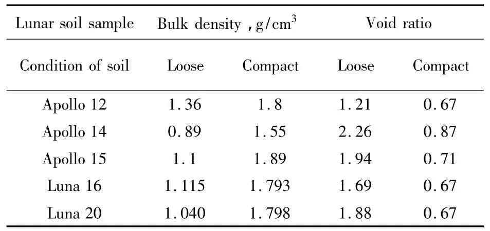
Table 1 Bulk density and void ratio[12]
Compressibility and shear strength parameters of the lunar soil samples were measured under different packing conditions,thus permitting the determination of general trends and relations of the physical and mechanical properties.Average values of the physical and mechanical properties of the lunar soil samples when compressed under static pressure are given in Table 2.

Table 2 Average compressibility and shear strength parameters of delivered lunar soil samples[12]
Mechanical properties of lunar soil are affected by ultrahigh vacuum,diurnal temperature extremes,cosmic and solar radiation on the Moon.Previous studies revealed that changes in environmental conditions affect the mechanical properties of lunar soil simulant.Significant increases in soil friction and cohesion have been measured after exposure to vacuum and high temperature.These studies led to the prediction that lunar soil may exhibit high friction and cohesion as a result of the environmental conditions on the Moon.Observations and measurements conducted during Surveyor(1966-1968),Apollo(1968-1972),and Luna(1959-1976)missions confirmed this prediction[19-20].
The physical and mechanical properties of the lunar soil make important impacts on the motion of the lunar lander after impact.The coefficient of the compressibility of the lunar soil influences the motion perpendicular to the lunar surface,and the friction coefficient of the lunar soil determines the motion parallel to the lunar surface to a great degree.
2 Lunar gravity simulation
As mentioned above,the landing performance of the lunar lander is principally influenced by the characteristics of the environment,so the lunar surface en-vironment should be simulated in the landing-impact tests on earth.Due to the limitation of the ground conditions,it is very difficult to simulate the full environment elements[3],but the key factor which influences the landing performance of the lunar lander,such as lunar terrain and lunar soil,should be considered.
Another important issue is the lunar gravity,which is only one-sixth that of the earth gravity[21-22].So,the lunar gravitational field has to be simulated so as to obtain dynamic similarity in the tests.
2.1 Inclined-plane technique
The inclined-plane gravity simulator,which is used to simulate the reduced gravity,consists of a payload,an inclined plane and a cable playing as a suspension system(Fig.1).The payload is retracted with the cable(the cable is tight)to the desired releasing location.Then it is released and allowed to swing through an arc[21,23].At the time that the suspended payload lands on the inclined surface,the relationship between the simulated weight(Fs)and the actual weight(Fa)is given by

Where,θis the angle of the landing surface relative to the vertical earth-gravity vector,which indicates the inclination of the landing surface.
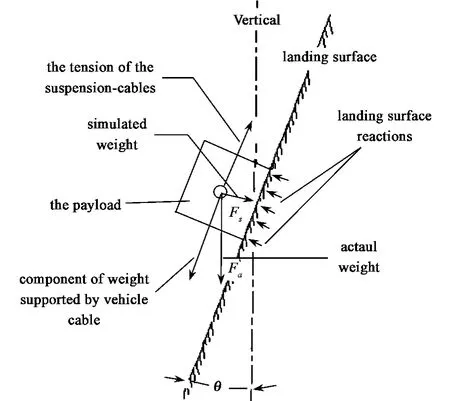
Fig.1 Principle of the inclined-plane technique
In the case of the lunar gravity,the simulated weight should be equivalent to 1/6 of the actual weight,therefore,sinθ=1/6,so the angle of inclination is given by

When the inclined-plane simulator is used in the tests,the lunar gravity is obtained by cable suspension and by inclining the model and the landing surface at the required angle relative to the vertical earth-gravity vector(9.5°).The model is essentially free to translate in a single two-dimensional plane normal to the landing surface(Fig.2)and to rotate about an axis normal to this plane.All other motions are constrained[23].
It is clear that this gravity simulator can be used to simulate another gravity which is lower than earth’s gravity by means of making a slight adjustment to the inclination angle of the landing surface,and the needed vertical impact velocity can be obtained easily by adjusting the releasing location.However,in order to simulate a needed gravity exactly,there are two matters needing attentions.(1)The cable must be tight in the process of moving,including the moment of landing;(2)The cable must run parallel to the landing surface at the moment of landing,and then the moving direction of the payload is perpendicular to the inclined surface.
2.2 Slide-wheel balanced technique
As shown in Fig.3,the general configuration of the gravity simulator consists of a payload m connected by a cable passing through overhead pulleys to a counterweight m'[24-25].
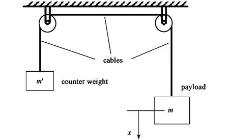
Fig.3 Principle of the slide-wheel balanced technique
The acceleration of the payload m is equal to that of the counterweight m'.So,the downward acceleration of the payload is given by

Where,f is the vertical lifting force of the cable,and g is the acceleration due to gravity on earth[24].At the same time,a is the downward acceleration of the payload,which is given by
For simulating the lunar gravitational field,a should be equal to g/6,therefore

Shown as the three equations above,the lunar gravity can be obtained successfully as long as the mass of the counterweight is equal to 5/7 of the mass of the payload.
Sometimes,the Slide-wheel balanced technique is adopted to simulate the lunar gravity in another way.The basic principle involves dropping the payload onto a relatively massive impact surface which is undergoing the desired acceleration relative to the freely falling payload.The effective gravitational acceleration acting on the payload during impact is then the difference between earth’s acceleration due to gravity and the acceleration of the impact surface[26].
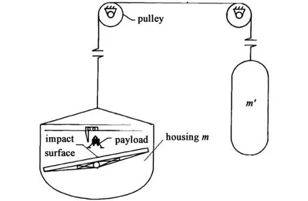
Fig.4 Application of the Slide-wheel balanced technique
As depicted in Fig.4,the general configuration of the gravity simulator consists of a payload and housing m(including an impact surface)connected by a cable passing through overhead pulleys to a counterweight m'[26].During a typical test sequence the payload is released at the desired horizontal velocity from a suitable mechanism located above the impact surface.The payload then gains the desired vertical impact velocity by free fall under 1g conditions.For the gravitation acceleration of the Moon,a should be equal to 5g/6,therefore m'is equal to 1/11 of m(calculated by function 4).
In the process of moving,the vertical acceleration of the payload is the earth’s acceleration due to gravity(g),while that of the housing m is 5g/6.So,the effective gravitational acceleration acting on the payload during impact is g/6.
2.3 Suspending technique
Simulation of the lunar gravity can be achieved by employing cables as a suspension system to act trough the center of the gravity of the payload(Fig.5).One end of the cables is attached to the payload through a gimbal which provides freedom of motion in pitch,roll,and yaw,and the other end is attached to a hoist which is installed on a fixed plane.The hoist employs a servocontrolled hydraulic system to drive the cables up and down in response to the motions of the payload[27-28].
Under the control of the servocontrolled hydraulic system,the cables provide a vertical lifting force which is equal to 5/6 of the weight of the payload.So,there is only 1/6 of the gravitational force left to provide the acceleration due to the lunar gravity[27,29].
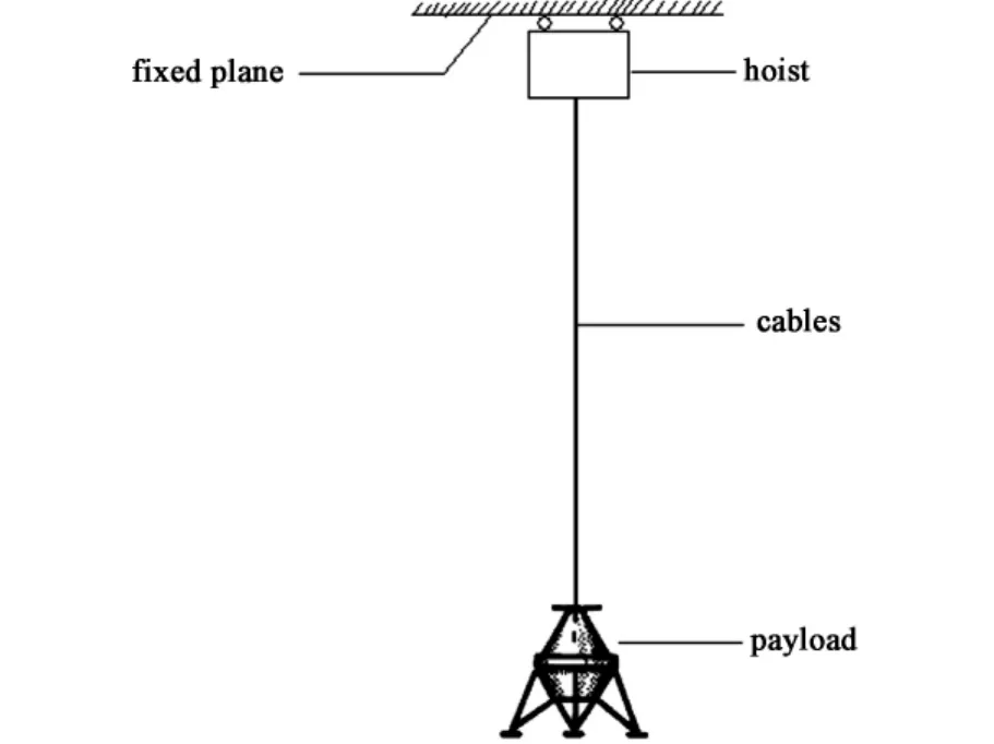
Fig.5 Application of the suspending technique
Each technique for simulating the lunar gravity has its own advantages and restrictions.(1)When the inclined-plane technique is used,the payload is allowed to move in the directions both parallel and perpendicular to the landing surface,and what’s more the initial velocities of the payload can be attained easily.However,the payload is under lunar gravitational field just at the moment of impact.Then,the actual motions of the lunar lander before falling to the lunar surface don’t appear;(2)In comparison with the inclinedplane technique,the payload is always under the simulated lunar gravitational field when the suspending technique is mooted.However,the motion of the payload parallel to the landing surface is restricted,and the controlling system of the simulator must control the force imposed to the payload by the cables precisely enough in the process of simulating;(3)In comparison with the technique else,the process of the simulating is not need to be controlled when the slide-wheel balanced technique is used,but the motion of the payload parallel to the landing surface is restricted also.In the process of preparing for the landing-impact tests,the technique for simulating the lunar gravity should be chosen reasonably by taking the purpose of the tests into attention.
3 Landing-impact tests
3.1 Test models
According to the purposes of the landing-impact tests researches,the full-scale model and the 1/6-scale model were designed.The full-scale model(Fig.6[21])has the geometry,construction and mass-inertia properties of the prototype,so it bears the actual dynamic loads and conditions which are imposed on the prototype at impact.
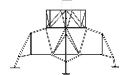
Fig.6 Construction of the test model
The construction of the model is symmetrical and trussed.Four steel outrigger trusses provide the attachment points for the landing-gear struts.The frame is designed to accommodate the necessary ballast to approximate the mass and inertial properties of the lunar lander.The model does not duplicate the elastic characteristics of the prototype lunar lander body[21].All available mass is used for ballast and structure,and the result is the model both stronger and less flexible than the prototype.Each of the four landing-gear assemblies consists of a primary strut(with a footpad at its lower end)and two secondary struts.The primary strut consists of an inner cylinder,an outer cylinder connected through a universal joint at its upper end to the outrigger truss,and a crushable aluminum honeycomb cartridge that acts in compression to absorb energy.Each secondary strut consists of an inner cylinder connected through a sleeve-journal universal joint to the outer cylinder of the primary strut,an out cylinder connected through a universal joint to the outrigger truss,and honeycomb cartridges which absorb energy while the double-acting secondary strut is lengthening or shortening[30-31].
So as to assure that the model tested bears a remarkable dynamic similarity to the prototype at impact,the shock-absorber material used in the models is same to the prototype.Then,the exact scale factor of the shock-absorber is provided.The two models are dynamically similar,because the important parameters,such as mass,center-of-gravity location,mass moment of inertia,landing-gear geometry,and energy-absorption characteristics,are adequately scaled for comparative purposes[21,23].Scale factors relating the 1/6-scale model parameters to the full-scale are given in Table.3.
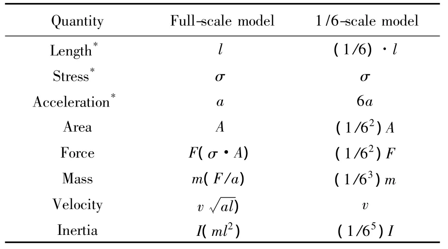
Table 3 Scale factors of the models[23,32]
3.2 Test apparatus and procedure
Two kinds of tests have been conducted for the landing-impact investigation.The one is the full-scale test with the simulated lunar gravitational field acting,and the other is the 1/6-scale test with the earth’s gravitational field acting.
3.2.1 Full-scale tests
In order to subject the structural components of the prototype lunar lander to the dynamic loads and conditions imposed during lunar-landing impact,fullscale tests are needed.To conduct such full-scale tests on earth,lunar gravity must be simulated.A number of full-scale landing-impact tests were conducted at the NASA Langley Research Center in 1960’s[30],and various methods were adopted to simulate the lunar gravity.Results of those tests indicated that the inclinedplane simulator is a suitable and economical method for conducting those full-scale tests.
The full-scale test is conducted by employing a pendulum apparatus to launch the full-scale model as a tethered body under the simulated lunar gravitational field(Fig.7).In generally,the facility of the fullscale test consists of an inclined-plane landing surface and a support cable,whose combination maintains the desired gravity reaction on the test model at impact.The support cable is also used as a pendulum device for obtaining the desired impact speed and attitude relative to the landing surface[23].
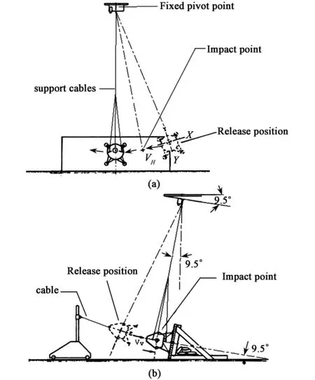
Fig.7 The process of the full-scale test
The model is retracted to a release position from which it is allowed to swing in an arc to the landing surface.During the swing the model impacts the landing surface vertically at a point along the flight path.The desired landing speed along the flight path is obtained from the gravitational force by adjusting vertical and horizontal(parallel to the landing surface)distances of the model from the release point to the impact point[23].
The inclined-plane simulator is adopted to simu-late the lunar gravitational field in this test,so the landing surface angle relative to the vertical earth-gravity vector is9.5°.In order to assure that the model impacts the landing surface vertically,the support cable must be parallel to the landing surface at the moment of impact.The full-scale simulator adequately reproduces the landing-impact dynamics and is suitable for conducting detailed studies of the lunar lander at impact.
3.2.2 1/6-scale tests
Test of the 1/6-scale dynamic model has been made to develop and evaluate the techniques for conducting full-scale landing-impact tests under the simulated lunar gravity[32].The 1/6-scale test is conducted by launching the 1/6-scale model as a free body by means of a four-bar pendulum[21,23](Fig.8).The pendulum can launch the model in a given direction with controlled horizontal and vertical impact velocity components.The model and the pendulum are connected through a vacuum seal between the plate on the top of the model and a mating plate with a seal on the pendulum[33].
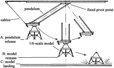
Fig.8 The process of the 1/6-scale test
The pendulum with the 1/6-scale model at the desired attitude is retracted to the point A,from where it is released and allowed to swing through an arc of vertical height AB[34].The vacuum seal is broken to release the model at point B at a horizontal velocity Vhwhich is approximately equal to a free-fall velocity for the vertical distance AB.Then,the model moves following a ballistic trajectory and drops a vertical height BC for the desired vertical velocity Vv.The combination of the horizontal velocity at release point B and the desired vertical velocity at impact determines the flightpath trajectory of the model after release[34-37].Finally,the model lands on the landing surface at impact point C.
According to the law of conservation of the mechanical energy,the horizontal velocity Vhand the vertical velocity Vvof the test model at the landing point Care given by

Where,hABis the vertical distance between the pendulum releasing point A and the model releasing point B,and the hBCis the vertical distance between the model releasing point B and the landing point C.Then,the desired vertical velocity and horizontal velocity of the model at impact are obtained by making adjustment to the two vertical distances.
3.3 Landing mode simulation
Numerous slopes,rocks and craters distribute on the lunar surface,and what is more the distribution is very complicated.So,when the lunar lander lands on the lunar surface,lots of landing modes are likely to appear,such as the 1-2-1 mode,2-2 mode and asymmetrical modes.Because the landing mode makes strong influence on the landing performance of the lunar lander,it should be simulated in the landing-impact tests on earth.As illustrated in Fig.8[34],The desired landing mode is obtained by constructing a step on the landing surface,whose height and location are calculated accurately according to the requirements of the test researches.
In the landing mode depicted in the Fig.9(a),three legs impact the landing surface at the moment of the model impacting the surface initially[34,38].With the moving of the model forward,all of the legs impact the surface,and absorb the impact energy.Severe landing of a single leg is obtained for the condition illustrated in the sequence of Fig.9(b).Essentially,only two legs are involved in this case and high acceleration resulted when the leading-leg shock absorbers are bottomed.

Fig.9 Technique for simulating the landing mode
4 Conclusion
(1)The lunar surface environments are complicated and harsh.The terrain,the physical and mechanical characteristics of the lunar soil at the landing site make great impacts on the buffering performance of the landing system,the landing stability,and the motiom of the lunar lander after impacting on the lunar surface.
(2)During the long-lasting researshes,many techniques are invented to simulate the lunar gravity,and each of the techniques has its own characteristics.The most reasonable technique for a test should be chosen by taking the purpose of the test and the objective conditions into attention.
(3)Each kind of the tests has its own strength and weakness.The dynamic state of the prototype lunar lander at impact is reproduced in the full-scale tests,but the major premise is that the lunar gravity is simulated.The 1/6-model is tested under earth’s gravity,but the test results have to be scaled.
[1]Li D Y.On moon resources and lunar exploration by spacecrafts[J].Spacecraft Recovery and Remote Sensing,2004,25(1):60-64(in Chinese).
[2]Zou Y L,Ou-yang Z Y,Xu L,et al.Lunar surface environmental characteristics[J].Quaternary Sciences,2002,22(6):533-539(in Chinese).
[3]Fan SC,Feng Y Q.The experimental facility for lunar rover development[J].Spacecraft Environment Engineering,2007,24(2):85-87(in Chinese).
[4]Chen JB.Investigation on the soft-landing design for lunar lander and the key technologies[D].Nanjing:Nanjing University of Aeronautics&Astronautics,2007(in Chinese).
[5]Victor L V,Emilio A B.Impact dynamic research facility for full-scale aircraft crash testing,NASA TN D-8179,1976.
[6]Claude B C,Emilio A B.Light airplane crash tests at there flight-path angles.NASA Technical Paper 1210,1978.
[7]Karen E J,Edwin L.A survey of research performed at NASa langley research center’s impact dynamics research facility[C]//44th AIAA/ASME/ASCE/AHSStructures,Structural Dynamics,and Materials Conference,Norfolk,2003.
[8]Lunar surface models NASA space vehicle design criteria environment.NASA SP-8023,1969.
[9]Niranjan SR,Bruan E W.Considerations for the design of lunar rover structures and mechanisms for prolonged operations in the lunar environment[J].AIAA 93-0993,1993.
[10]Fang SC,Jia Y,Xiang SH,et al.A preliminary study on simulation of lunar surface terrain[J].Spacecraft Environment Engineering,2007,24(1):15-20(in Chinese).
[11]Shi X B,Li Y Z,Huang Y,et al.The conceptual design of lunar surface environment simulation system[J].Engineering Science,2006,8(11):93-97(in chinese).
[12]Gromov V.Physical and mechanical properties of lunar and planetary soil[J].Earth,Moon and Planets,1999,80:51-72.
[13]Carr M.The surface of mars[M].New Haven:Yale University,Press,1981.
[14]Carrier W D.Lunar soil grain size distribution[J].The Moon,Vol.6.1973.
[15]Carrier WD,Mitchel JK,Mahmood A.The nature of lunar soil[J].Journal of the Soil Mechanics and Foundations Division,ASCE,1973,99:813-832.
[16]Zhang Y C,Ou-yang Z Y,Wang S J,et al.Physical and mechanical properties of lunar regolith[J].Mineral Petrol,2004,24(4):14-19(in Chinese).
[17]Taylor L A,Schmitt H H,Nakagawa M.The lunar dust problem:from liability to assets.AIAA 2005-2510.
[18]Marshall Space Flight Center Johnson Space Center.Lunar Regolith Simulant Material Workshop,2005.
[19]Howard A P.Effects of surface cleanliness on lunar regolith mechanics.AIAA 96-0015,1996.
[20]Ye P J,Xiao F G.Lunar environmental issues of lunar exploration project[J].Spacecraft Environment Engineering,2006,23(1):1-11(in Chinese).
[21]Ulysse J B.Evaluation of a full-scale lunar-gravity simulator by comparison of landing-impact tests of a full-scale and a 1/6-scale model[J].NASA TN D-4474,1968.
[22]Jaquet B M.Simulator studies and lunar landing techniques.NASA TM X-51395,1965.
[23]Ulysse JB.Model investigation of technique for conducting fullscale landing-impact tests at simulated lunar gravity.NASA TN D-2586,1965.
[24]Wang SC,Deng Z Q,Hu M,et al.An experimental method for simulating lunar lander low gravitation landing[J].Journal of the Shanghai Jiaotong University,2005,39(6):989-992(in Chinese).
[25]Deng Z Q,Wang S C,Hu M,et al.Elementary exploring for technology of microminiatrue space lander[J].Missiles and Space Vehicle,2003(2):1-6(in Chinese).
[26]Huey D,Carden,Robert W,Herr,et al.Technique for the simulation of lunar and planetary gravitational fields including pilot model studies.NASA TN D-2415,1968.
[27]Tbomas C B,Donald E H.Operational features of the langley lunar landing research facility,NASA TN D-3828,1967.
[28]Siegfried J G.Zero-G devices and weightlessness simulators[M].Washington:National Research Council,Publication 781,1961.
[29]Gene J M,Harold P W.Handling qualities and trajectory requirements for terminal lunar landing,as determined from analog simulation.NASA TN D-1921,1963.
[30]Ulesse J B.Full-scale dynamic landing-impact investigation of a prototype lunar module landing gear.NASA TN D-5029,1969.
[31]William F R.Apollo experience report-lunar module landing gear subsystem,NASA TN D-6850,1972.
[32]Ulysse J B.Landing characteristics of a winged reentry vehicle with all-skid landing gear having yielding-metal shock absorbers.NASA TN D-1496,1962.
[33]Robert W H,H W L.Dynamic model investigation of touchdown stability of lunar-landing vehicles,NASA TN D-4215,1976.
[34]Ulysse JB.Characteristicsof a lunar landing configuration having various multiple-leg landing-gear arrangements.NASA TN D-2027,1964.
[35]Claude B C,Emilil A B.Light airplane crash tests at three roll angles,NASA TN D-1477,1979.
[36]Victor L V,Emilil A B.Light airplane crash tests at three pitch angles.NASA TN D-1481,1979.
[37]Victor L V,Robert J H.Crash tests of four identical high-wing single-engine airplanes,NASA TN D-1699,1980.
[38]Walton W C,Jr R W.Studies of touchdown stability for lunar landing vehicles[J].AIAA,January 20-22,1964.
- 宇航学报的其它文章
- 欠驱动刚性航天器可行轨迹生成算法研究

