电泳法制备TiO2纳米管/纳米颗粒复合薄膜的电化学阻抗谱分析
汪文立 林 红 张罗正 李 鑫 崔 柏 李建保
(清华大学材料科学与工程系,精细陶瓷与先进工艺国家重点实验室,北京 100084)
Owing to its simple preparation process,low production-cost, theoretically high conversion efficiency,and short time for the energy payback,dye-sensitized solar cells(DSCs)are attracting extensiveattention[1-5].DSCs require a photoanode to provide both a large surface area to maximize dye adsorption and efficient electron transport to deliver the electrons to the collection elec-trode.Generally,a porous film consisting of nanocrystalline TiO2particles is usually used as the photoanode.Electrons that are transported through this kind of film always involve a slow trap-limited diffusion process and experience a random walk, which leads to a limit on the overall performance of the DSC. Recently,the introduction of one-dimensional(1D)nanostructures into the photoanode is becoming a trend as they may provide a faster and direct transport pathway for the electrons[6-10].Research on films consisting of 1D nanostructures is often focused on their photovoltaic performance.However,studies on how 1D nanostructures affect the photovoltaic performance have rarely been reported[11].
Electrochemical impedance spectroscopy(EIS)is well-known as a useful technique to investigate kinetic processes in DSCs[11-14]. EIS measurements have the advantage of obtaining numerous electrochemical parameters at the same time,including the electron transport in the nanoporous photoanode film,diffusion of the redox species in the electrolyte,and charge transfer at the counter-electrode surface and at the photoanode/electrolyte interface.DSC is a type of photoelectrochemical cell,thus the electrochemical properties of the photoanode is crucial to the cell′s performance.In this study,the electrochemical properties of 1D nanostructures were studied in order to understand the influence of 1D nanostructures on DSCs.
In this article,a composite TiO2film consisting of nanotubes and nanoparticles was prepared through electrophoretic deposition(EPD),a method often used to fabricate TiO2films[15-17].The influence of the composition of the TiO2film on the photovoltaic performance of the DSCs was studied.EIS measurements were conducted to scrutinize the electrochemical properties of these composite TiO2films.On the basis of the data derived from the EIS analysis,the contributions of titania nanotubes(TNTs)and a kind of large TiO2particle(particle size of 100 nm)were systematically investigated.The correlation between the total resistance of the DSC and the cell′s photo-to-electricity conversion efficiency was also discussed.
1 Experimental
1.1 Electrophoretic deposition of TiO2film
All chemicals are of analytical grade and used without further purification.The starting powder used in this study consisted of titanate nanotubes(TNTs),P25 particles(Degussa 99.5%,Germany,mean particle size ca 25 nm,anatase 80%,rutile 20% denoted as PPs)and TiO2particles with an average particle size of 100 nm(Degussa 99.5%,Germany,labeled as LPs,namely large particles,anatase).TNTs with outer diameter and length of 9 nm and 200-400 nm,respectively,were synthesized through hydrothermal treatment[18].The total mass of the starting powder was 0.05 g.Polyvinyl butyral(PVB,99.9%,average molecular weight:19000)was used as a dispersant;a mixture of anhydrous ethanol(49 mL)and deionized water(1 mL)was used as solvent. The suspension was treated with stirring(5 min),ultrasonication (10 min),and further stirring(5 min)in order to obtain a homogeneous dispersion.
For electrophoretic deposition(EPD),ITO-glass(25 Ω·□-1, China Building Materials Academy)served as the substrate and cathode.The anode was a plate of stainless steel.The distance between the two electrodes was 2 cm,and the deposition was performed for 5 min at a voltage of 27.5 V.After deposition,the film was carefully drawn out of the suspension,dried in air for 10 min,and then calcined at 450℃for 0.5 h.After calcination, amorphous TNTs in the composite film were transformed into anatase TNTs[18].The film thickness(L)was 9 μm.
1.2 Assembly of DSC
The assembly procedure of the DSC was exactly the same as that mentioned by Li et al.[19].Briefly,the TiO2films were immersed overnight in an anhydrous ethanol solution of 5 mmol· L-1ruthenium(2,2′-bipyridyl-4,4′-dicarboxylate)2(NCS)2(N719 dye,Kojima Chemicals Corporation,Japan)and then dried at room temperature to form photoanodes.One drop of an iodinebased electrolyte solution was deposited onto the surface of the dye-adsorbed TiO2films.The electrolyte solution was composed of 50 mmol·L-1iodine(I2),500 mmol·L-1lithium iodide(LiI), and 500 mmol·L-1tert-butyl pyridine dissolved in acetonitrile. Platinized ITO-glass was used as a counter-electrode.The active area of the photoanodes was 0.235 cm2.
1.3 Characterization
Photovoltaic properties were measured under AM1.5 solar condition using a 500 W metal halide lamp(CMH-250,Photovoltaic Instrument Factory of Beijing Normal University,China). Photochemical behavior was investigated using a source meter (Keithley-2400,Keithley Co.Ltd.,USA).Electrochemical impedance spectroscopy(EIS)measurement was carried out by applying a forward bias at an open-circuit-voltage(OCV)under the AM1.5 solar condition,with an ac amplitude of 10 mV over a frequency range of 0.1 to 1000 Hz using a CHI660B electrochemical analyzer(CHI604A,CH Instrument Corp.USA).Specific surface area was measured using the nitrogen adsorption method(BET method)(NOVA4000,Quantachrome Instruments Corp.USA).
2 Results and discussion
2.1 Influence of the mass ratio of LPs to PPs
In order to raise the deposition speed and introduce scattering centers into the photoanode,LPs were added into the suspension[20].In this section,only two kinds of particles,LPs and PPs, were used in the starting powder.The photocurrent density(J)-voltage(V)characteristic curves of the LP-PP composite DSCs are shown in Fig.1,and the corresponding efficiencies are summarized in Table 1.It can be observed that the efficiency of the composite DSC suffers little alteration when the mass fraction of the LPs(wLP)is very low,but it drops significantly with the increasing content once the content is beyond 20%.Therefore,it can be deduced that photoanodes with LP content of no more than 20%are suitable for DSCs.
To obtain the optimum content for LPs and to examine the contribution of the LPs to the photoanodes,EIS measurements were conducted,with the Nyquist representation displayed in Fig.2.For analyzing the Nyquist diagrams,an equivalent circuit for DSCs,as illustrated in Fig.3,is employed[21-22].In this circuit, RSis the series resistance of the sheet resistance of the ITO-glass,Pt counter-electrode and the resistance of the electrolyte; RTCOand CTCOare the resistance and capacitance of the trsnsparentconductingoxide(TCO)/TiO2/electrolyteinterface,respectively;Rt(=rtL,L is the film thickness)is the electron transport resistance;Rct(=rct/L)is the charge-transfer resistance related to the recombination of electrons at the TiO2/electrolyte interface;Cμ(=cμL)is the chemical capacitance.Zdis the Warburg element showing the Nernst diffusion of I-3in the electrolyte;RPtand CPtare the charge-transfer resistance and the capacitance at the counter electrode,respectively[14].

Fig.1 Photocurrent density(J)-voltage(V)curves of the LP-PP composite DSCs
The charge transport properties of the LP-PP composite photoanodes derived from the Nyquist diagrams using Zview software,based on the procedure proposed by Bisquert[23],are presented in Table 1.The lifetime(τ),diffusion coefficient(Deff),and diffusion length(Ln)could be further calculated using τ=RctCμ, Deff=L2(RtCμ)-1,Ln=(Deffτ)1/2.

Fig.2 Nyquist plots of the LP-PP composite DSCs
Table 1 shows that the efficiency of the DSCs with LP-PP composite films increases when the mass fraction of LPs is below 20%.However,the efficiency drops rapidly when the mass fraction of LPs rises above 20%.To understand how this trend is formed,the electrochemical properties were investigated.It is widely accepted that the diffusion of an electron within the photoanode film is in competition with the recombination process at the photoanode film/electrolyte interface.When the LP content is increased,Rctstays almost the same while Rtalters.When the mass fraction of LPs is 20%,Rtreaches a minimum of 44.97 Ω. This leads to Rct/Rtobtaining the highest value for the 20%sample when the diffusion process is faster than the recombination process,as compared with the other samples.Thus,when the mass fraction of LPs is 20%,the optimum cell performance is obtained.When the LP content is further increased,the Rct/Rtvalue decreases which is in accordance with the variation of the efficiency.

Fig.3 Equivalent circuit used for DSCs

Table 1 Efficiencies of the LP-PP composite DSCs based on photoanodes with different mass fractions of LPs (wLP)and corresponding electron transport properties determined by impedance analysis
To understand how the LP-PP composite films benefit the DSC,the characteristics of the composite films are considered.It can be found from Table 1 that the diffusion coefficient Deffincreases with increasing LP content.It is known that multiple trapping/detrapping events occur within the grain boundaries during electron diffusion process.Due to a smaller number of grain boundaries,the LP-PP composite films exhibit a lower resistance to the electron transport.However,the chemical capac-itance,which is related to the surface states of the nanoparticles, achieves its maximum at LP content of 20%leading to the lifetime(τ)and diffusion length(Ln)obtaining the highest values. This explains why the diffusion process is faster than the recombination process.Another issue that should be addressed is that the crystal form of the LPs is anatase,which is demonstrated to be an ideal choice for a DSC based on TiO2films[24],while that of the PPs includes anatase and rutile.In addition,the introduction of LPs into the photoanode could increase the traveling length of light within the film,thus an augmentation on the lightharvesting,which is favorable for the increase of the incidentphoton-to-current conversion efficiency(IPCE),is achieved.All of the three factors above may contribute to the optimum performance at the LP content of 20%.

Table 2 Specific surface area of LP-PP composite with different mass fractions of LPs(wLP)
In a DSC,the photoanode is always required to afford an effective surface area as large as possible;however,the films with LPs have a lower surface area because of the relatively smaller specific surface area for LP itself.Table 2 shows the specific surface area(S)of the LP-PP composite with different mass fractions of LPs(wLP).As wLPincreases,the specific surface area of the composite film decreases,leading to the lowest dye absorption.Moreover,the lifetime(τ)and diffusion length(Ln)also decrease with increasing wLP.Thus,when the mass fraction of LPs is larger than 20%,the performance of the DSC tended to decrease.
Combining the above analyses,the optimum mass fraction of LPs for an LP-PP composite DSC is around 20%.In the following sections,the ratio of LPs to PPs is fixed at a constant of 1∶4.
2.2 Solar cells based on TNT-LP-PP composite films
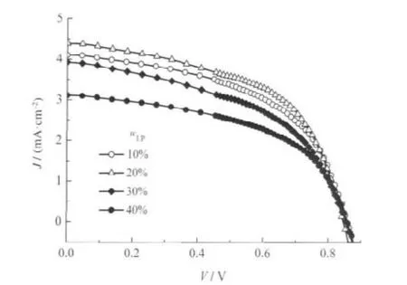
For TNT-LP-PP composite films,the mass fraction of TNTs varies from 10%to 40%.The J-V curves and the corresponding efficiencies of the TNT-LP-PP composite DSCs are shown in Fig.4 and listed in Table 3,respectively.It is observed that the efficiencies first increase with the increase in TNT content,and then flatten out with a slight decline when the content is beyond 20%.Although a rough conclusion can be drawn that the TNT content for an optimum TNT-LP-PP composite DSC is around 20%,the mechanism of the trend for the light-to-electricity efficiency needs to be elucidated.
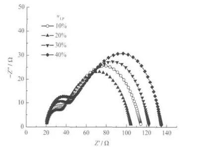
EIS measurements were conducted for these cells.The charge transport properties derived from the Nyquist plots shown in Fig. 5 are displayed in Table 3.It has been found that the relative value between Rctand Rtreflects the competition level of the electron diffusion through the photoanode film with respect to the recombination process.From Table 3,it can be seen that the value of Rct/Rtexhibits a similar trend to that of the conversion efficiency,implying that the incorporation of TNTs could increase the electron transport rate.Compared with the nanoparticle composite films shown in Table 1,the TNT/particle film decreases Rtremarkably at the TNT concentration of 20%.The reason for this is the high diffusion coefficient(Deff)which shows that the electrons move faster in the nanotubes.It is also found that the electron lifetime is larger in the nanotube than that in the particles(as shown in Table 1),which is due to the higher chemical capacitance(Cμ).TNTs have a high diffusion coefficient and long lifetime,thus,the diffusion length for the TNT/nanoparticle composite film achieves a maximum at the TNT concentration of 20%.Considering that the film thickness is 9 μm,the high diffusion length of 12.71 μm benefits the electron transport in the TNT/nanoparticle film which leads to better performance.

Fig.4 Current density-voltage curves of the TNT-LP-PP composite DSCs

Fig.5 Nyquist plots of the TNT-LP-PP composite DSCs

Table 3 Efficiencies of TNT-LP-PP composite DSCs based on photoanodes with different mass fractions of TNTs, and the corresponding electron transport properties derived from EIS

Table 4 Specific surface area of TNT-LP-PP composite with different mass fractions of TNTs(wTNT)
Table 4 shows the specific surface area of the TNT-LP-PP composite with different mass fractions of TNTs(wTNT).As the mass fraction of TNTs increases,the specific surface area increases significantly as 1D nanostructures can effectively enlarge the surface area[25].However,compared with the LP-PP composites without nanotubes,the performance of the LP-PP-TNT composite deteriorates.There are other factors affecting the TNTs to improve the performance of the DSC.TNTs have been verified to show a crystal form of anatase in our previous study[18],but its crystallinity is much lower compared to those of LPs and PPs.A lower crystallinity results from a higher concentration of defects, which always acts as a trapping center in the photoanode films. The relatively smaller Deffmay be ascribed to this.The TNTs may also obstruct the diffusion of I-/I-3in the electrolyte[26].To further raise the performance of the TNT-LP-PP composite DSC,TNTs with fewer defects should be explored.
Based on the results in Table 3,the optimum properties for the electron transport always locate around 20%of TNT content.It is found that the incorporation of TNTs can increase the diffusion length and specific surface area of the TiO2film. However,with the influence of low crystallinity,nanotube structure,and other factors,the performance of the cell is not improved which is in accordance with other research[26].Although a further exploration should be carried out,the TNT content of 20%is regarded as the optimum for the TNT-LP-PP composite DSCs here.
3 Conclusions
EIS measurements were conducted to analyze the properties of the dye-sensitized solar cells(DSCs)based on various TiO2composite films.It is found that large particles increase the charge diffusion and cell performance before the mass fraction of large particles reaches 20%.TNTs are found to reduce the charge transport resistance remarkably which shows the advantage of 1D nanostructures in conducting electrons in TiO2thin film.The optimum mass ratio of TNTs∶LPs∶PPs is 20∶16∶64.To improve the application of TNTs in DSCs,further research in improving their crystallinity and structures should be carried out.
1 O′Regan,B.;Grätzel,M.Nature,1991,353:737
2 Nazeeruddin,M.K.;De Angelis,F.;Fantacci,S.;Selloni,A; Viscardi,G.;Liska,P.;Ito,S.;Takeru,B.;Grätzel,M.J.Am.Chem. Soc.,2005,127:16835
3 Wei,M.D.;Konishi,Y.;Zhou,H.S.;Yanagida,M.;Sugihara,H.; Arakawa,H.J.Mater.Chem.,2006,16:1287
4 Kroon,J.M.;Bakker,N.J.;Smit,H.J.P.;Liska,P.;Thampi,K.R.; Wang,P.;Zakeeruddin,S.M.;Grätzel,M.;Hinsch,A.;Hore,S.; Würfel,U.;Sastrawan,R.;Durrant,J.R.;Palomares,E.;Pettersson, H.;Gruszecki,T.;Walter,J.;Skupien,K.;Tulloch,G.E.Prog. Photovolt:Res.Appl.,2007,15:1
5 Murakami,T.N.;Ito,S.;Wang,Q.;Nazeeruddin,M.K.;Bessho, T.;Cesar,I.;Liska,P.;Humphry-Baker,R.;Comte,P.;Pechy,P.; Grätzel,M.J.Electrochem.Soc.,2006,153:A2255
6 Adachi,M.;Murata,Y.;Okada,I.;Yoshikawa,S.J.Electrochem. Soc.,2003,150:G488
7 Ngamsinlapasathian,S.;Sakulkhaemaruethai,S.;Pavasupree,S.; Kitiyanan,A.;Sreethawong,T.;Suzuki,Y.;Yoshikawa,S. J.Photochem.Photobiol.A-Chem.,2004,164:145
8 Tan,B.;Wu,Y.Y.J.Phys.Chem.B,2006,110:15932
9 Law,M.;Greene,L.E.;Johnson,J.C.;Saykally,R.;Yang,P.D. Nat.Mater.,2005,4:455
10 Baxter,J.B.;Aydil,E.S.Appl.Phys.Lett.,2005,86:053114
11 Ku,C.H.,Wu,J.J.Appl.Phys.Lett.,2007,91:093117
12 Kern,R.;Sastrawan,R.;Ferber,J.;Stangl,R.;Luther,J. Electrochim.Acta,2002,47:4213
13 Hoshikawa,T.;Ikebe,T.;Kikuchi,R.;Eguchi,K.Electrochim. Acta,2006,51:5286
14 Fabregat-Santiago,F.;Bisquert,J.;Palomares,E.;Otero,L.; Kuang,D.B.;Zakeeruddin,S.M.;Grätzel,M.J.Phys.Chem.C, 2007,111:6550
15 Lebrette,S.;Pagnoux,C.;Abélard,P.J.Eur.Ceram.Soc.,2006, 26:2727
16 Wang,N.;Lin,H.;Li,J.B.;Yang,X.Z.;Chi,B.Thin Solid Films, 2006,496:649
17 Tang,F.Q.;Uchikoshi,T.;Wawa,K.;Sakka,Y.J.Eur.Ceram. Soc.,2006,26:1555
18 Zhang,L.Z.;Lin,H.;Wang,N.;Lin,C.F.;Li,J.B.J.Alloy. Compd.,2007,431:230
19 Li,X.;Lin,H.;Li,J.B.;Wang,N.;Lin,C.F.;Zhang,L.Z. J.Photochem.Photobiol.A-Chem.,2008,195:247
20 Miyasaka,T.;Kijitori,Y.J.Electrochem.Soc.,2004,151:A1767
21 Fabregat-Santiago,F.;Bisquert,J.;Garcia-Belmonte,G.;Boschloo, G.;Hagfeldt,A.Sol.Energy Mater.Sol.Cells.,2005,87:117
22 Li,X.;Lin,H.;Li,J.B.;Li,X.X.;Cui,B.;Zhang,L.Z.J.Phys. Chem.C,2008,112:13744
23 Bisquert,J.J.Phys.Chem.B,2002,106:325
24 Park,N.G.;van de Lagemaat,J.;Frank,A.J.J.Phys.Chem.B, 2000,104:8989
25 Suzuki,Y.;Ngamsinlapasathian,S.;Yoshida,R.;Yoshikawa,S. Cent.Eur.J.Chem.,2006,4:476
26 Uchida,S.;Chiba,R.;Tomiha,M.;Masaki,N.;Shirai,M. Electrochemistry,2002,70:418
———动力工程系

