页轮干式磨削Ti6Al4V合金
霍文国 徐九华 傅玉灿 苏宏华
(南京航空航天大学机电学院,南京,210016,中国)
INTRODUCTION
Conventional titanium alloy Ti6Al4V,which accounts for between 50% and 60% of total titanium alloy production,is characterized by high tensile strength 1 100 MPa at 20°C combined with low density and good corrosion resistance.Such qualities explain why titanium alloys account for around 33% of engine weight in current commercial aircraft[1].Unfortunately,the unique physical and chemical properties that make titanium alloys suitable for many applications also contribute to the difficulties with which they are cut or ground.Additionally,its low heat conductivity increases the temperature at the tool/workpiece interface,thereby also affecting workpiece material adversely.The tendency of titanium alloys to bring surface damage is a disadvantage during machining operations[2].The damage appears in the form of heat affected zones and residual tensile stresses.Component failure could occur during service as a result of fatigue and stress corrosion[3].During grinding with the abrasive wheels,which has been one of the most popular processes for titanium alloy,short wheel life and severe surface abuse of ground workpiece are the important factors impairing their grindability.
Titanium alloys are generally utilized for parts requiring the greatest reliability,therefore,the surface roughness and any damage to the subsurface layers must be controlled[4].Dry machining and cooling with ecological cutting fluids have been receiving the increasing attention because of ecological impact of conventional cutting fluids.Ecological machining techniques will be considered as a necessity for manufacturing enterprises in future[5].
Although extensive researches have been conducted on the grinding of titanium alloys over the past decades with a specialization in the thermal damage to the workpiece[6-9],relatively fewer studies have been dedicated to identify the dry grinding with flap wheels.Flap wheels grinding is a machining process with a geometrically indeterminate cutting edge.In order to provide an optimizing technological basis for flap wheels grinding,the main objective of this paper is undertaken to elucidate grinding force,grinding temperature and surface integrity during dry grinding using zirconia alumina and silicon carbide flap wheels.
1 EXPERIMENTAL SET-UP AND CONDITIONS
Straight surface grinding experiments are conducted on a precision grinder with continuousgrinding mode. The experimental set-up is schematically illustrated in Figs.1, 2. The Ti6Al4V alloy workpiece is mounted on a KISTLER 9265B dynamometer to measure the grinding forces in three directions.The temperature of the grinding zone is measured by a constantan-workpiece thermocouple. The grinding temperature response is obtained by NI USB-621X signal collection system. The features of workpiece surfaces and the metallographic structure are observed by Hirox KH-7700 stereoscopic microscope and Quanta200 scanning electron microscope(SEM).The microhardness is measured with a HXS-1000A microhardness tester. The surface roughness of workpiece is measured using a Mahr Perthometer M1 instrument. The Ti6Al4V alloys is used in the experiments under annealed condition.The dimension is 160(L)mm×25(W)mm×8(H)mm,and the area of grinding surface is 160(L)mm×8(H)mm.
Two grinding flap wheels,i.e.,zirconia alumina and silicon carbide flap wheels are used in the experiments.The size of grits is 80/100 US mesh.The diameter and the rim width of the wheel are 25 and 20 mm for the zirconia alumina and silicon carbide flap wheels,respectively.The flap wheels of the grinding experiment are shown in Fig.3.
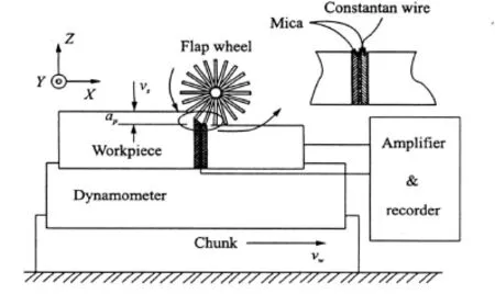
Fig.1 Schema of experimental set-up
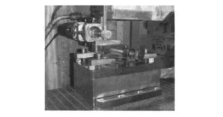
Fig.2 Experimental set-up
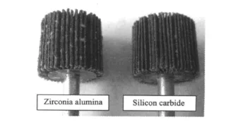
Fig.3 Flap wheels
2 EXPERIMENTAL RESULTS AND DISCUSSION
2.1 Grinding forces
In separate grinding passes of each parameter combination,the feed motion during stationary grinding is stopped and grinding forces are recorded. The displayed values of forces are average values of three measurements during grinding process and are low-pass filtered(20 Hz).In Fig.4,grinding force is depicted,i.e.,impact of the zirconia alumina and silicon carbide flap wheels for dry grinding is taken out.The zirconia alumina flap wheels show lower grinding forces in comparison to the silicon carbide flap wheels.Concerning the normal and tangential grinding forces,a reduction of 10%—20%and 5%—10%can be achieved.For zirconia alumina wheels,the grinding forces are nearly constant with further variations in comparison to silicon carbide flap wheel grinding.
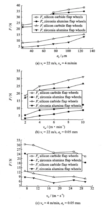
Fig.4 Grinding forces versus grinding parameters
For dry grinding with flap wheels,an increase of grinding forces with the increasing depth of cut apcan be observed in Fig.4(a).It shows that the increasing of force with the augment of apin the flap wheel speed vs= 22 m/s and the table speed vw= 4 m/min.Initially,grinding force remains minor change because the flap wheel is compressed.With the continuing increase of apduring dry grinding,the grinding forces is rapidly accelerated based on the increased contact lengths leading to more active grains and consequently the increased friction.It can be seen from Fig.4(b)that the forces slowly increase with the increasing of vw.The increase of vw brings a lesser distinctness influence to the grinding force thanap.Fig.4(c)shows the variation of grinding forces with vs under vw=4 m/min and ap=0.05 mm.With the increasing of vs,the grinding force is decreased gradually and the thickness of single grinding abrasive is reduced.The grinding force of the single abrasive is decreased, therefore, grinding forces during grinding decrease evidently.
2.2 Grinding temperature
The temperature response on the workpiece surface is measured using a grindable foil/workpiece thermocouple consisting of a constantan foil of 35 μ m thickness insulated on both sides by 10μ m sheets of mica and sandwiched between two pieces of a split workpiece.The workpiece acts as the other thermocouple pole.The signal from the foil/workpiece thermocouple is obtained by a single pass of the grinding flap wheel over the workpiece.The output from the foil/workpiece thermocouple is fed to a dynamic signal recorder.The representative signal from the foil/workpiece thermocouple is shown in Fig.5 at vs=22 m/s,ap=0.05 mm,vw=4 m/min by zirconia alumina flap wheels.
The zirconia alumina wheels show a lower grinding temperature in comparison to the silicon carbide flap wheel.For zirconia alumina wheel grinding,temperatures are almost constant with further variations in comparison to silicon carbide flap wheel grinding.In Fig.6,it can be seen that the workpiece temperature is increased slowly with ascending vw(Fig.6(a))because of the increasing of total ground abrasive contact length and effect of flap wheel combined with the increased vw.Nevertheless,table speed has no evident effect to the workpiece temperatures(Fig.6(b)).Concerning workpiece temperatures(Fig.6(c))during dry grinding,a significant temperature increase from 48°C to 305°C can be observed with the increasing of ap.As a side effect of higher temperatures,adhesion of workpiece material on the flap wheels occurs with larger ap.Thus,the friction between grinding wheels and workpiece further increases and contributes to higher temperatures.However,the material adhesion does not accumulate after many grinding operations without active cleaning of the grinding wheel′s surface.Instead,a stationary self-cleaning process occurs. Existent material adhesion completely disappears after grinding operations with low ap(ap≤75μ m).
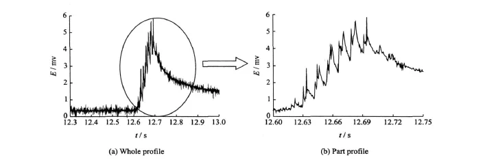
Fig.5 Representative original signal of flap wheel grinding temperature
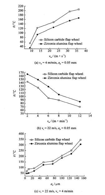
Fig.6 Relationship between the temperature of ground surface and the process parameter
2.3 Surface roughness and morphological features
The workpiece surface roughness is measured orthogonal to the grinding direction in the middle of the ground workpiece surface.Fig.7 shows the mean value of six measurements of the arithmetic average deviation value of the profile Ra.
Fig.7(a)shows the enlargement of surface roughness with increasing apfor both flap wheels resemble a good correlation to the grinding forces and temperature.The best surface roughness is achieved by the application of the zirconia alumina wheels caused by most amounts of grains with low ap.The intensified material adhesion for higher force and temperatures in dry grinding contributes to rough workpiece surfaces.
Fig.7(b)shows the evolution of surface roughness of workpiece machined with zirconia alumina and silicon carbide flap wheels versus grinding time.In both zirconia alumina and silicon carbide flap wheels,Ra is approximately 1.6μ m in the initial surface milled.Roughness increases at grinding time corresponding to the medium wear of the abrasive,ranging from 1.45 to 0.82 μ m.Finally,close to abrasive failure,roughness increases up to 0.82 and 0.89μ m,respectively.Good surface roughness is obtained up to abrasive failure.
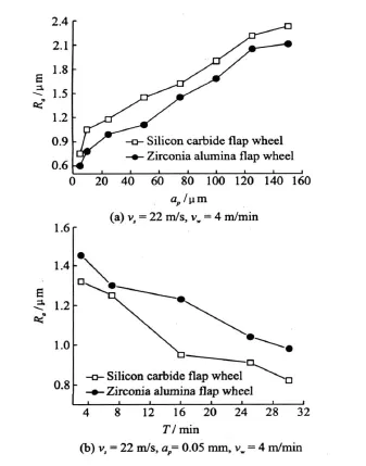
Fig.7 Surface roughness versus grinding parameter
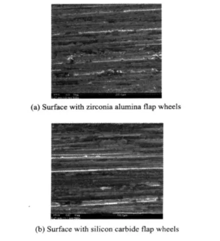
Fig.8 Surface morphology of ground workpiece(vs=22 m/s,ap=0.05 mm,vw=4 m/min)
Figs.8(a,b)show the morphological pictures of the ground surfaces of Ti6Al4V alloy produced by zirconia alumina and silicon carbide flap wheels,respectively.Grinding burn does not occur either for dry grinding experiments.Much fewer coating and scratch can be seen on the ground workpiece surfaces for flap wheel grinding.
2.4 Micro-structural changes
For investigation of the workpiece surface integrity microstructure sections of the workpiece are prepared for microhardness and metallographic analysis.For the microstructure analysis,the sections are etched for 20 s using 3% of alc.HNO3.
The different zones are identified by their different microstructures(see Fig.9).The same qualitative microstructural changes are observed in both zirconia alumina and silicon carbide flap wheel grindings,but more pronounced under the grinding condition of the silicon carbide flap wheels.Results obtained under this condition are shown in micrograph for a workpiece after 16 passes.Two regions A and B with different microstructure can be observed.

Fig.9 Microstructure of workpiece(vs= 22m/s,ap=0.05 mm,vw=4 m/min)
Region A,closer to the workpiece surface ground,with an depth about 40μ m,corresponds to the highest temperature.When titanium alloys are heated in oxygen containing ambient,a surface hardened zone is formed.This layer is referred to as the″alpha case″because oxygen and nitrogen stabilize alpha phase.This agrees well with microhardness observations.
Region B,presents different microstructures because of the decrease of the temperature with increasing distance from the ground surface.A feebleness distortion in microstructure is observed.Plastic deformations during machining are caused by mechanical forces from the grinding abrasive acting upon the workpiece. Additional deformation can occur as a consequence of temperature gradients due to local heating of the machined surface area.
Fig.10 shows marks resulting from microhardness tests in the same specimen obtained from cross section machined with dry grinding.Microhardness(Vickers)is measured in eight points(located at a distance from machined surface ranging from 20μ m to 160μ m in two lines perpendicular to the machined surface direction).
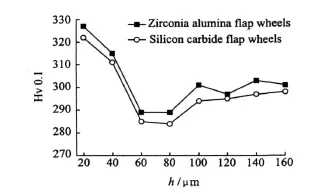
Fig.10 Micro-hardness of surface layer(vs=22 m/s,ap=0.05 mm,vw=4 m/min)
In the zone close to machined surface(distance 20μ m)value of about 325 Hv is obtained,approximately 10% greater to hardness obtained in material before machining.In the zone close to machined surface(distance 60μ m)value of about 280 Hv is obtained,approximately 5% lower to the hardness obtained in material before machining.
3 CONCLUSIONS
This paper is focused on grinding forces,grinding temperature and surface integrity during dry grinding of Ti6Al4V alloy.Experiments are carried out on zirconia alumina and silicon carbide flap wheels to observe the grinding grindability.Some conclusions can be obtained:
(1)It is proved in the grinding experiment that there is no grinding burn of Ti6Al4V alloys,and grinding heat-affected zone is small with two kinds different abrasive flap wheels when grinding parameter with larger vs,lower ap and medium vw(vs=13—31 m/s,-ap=0.025 0.01mm,vw=2—6 m/min).It can be seen that flap grinding has excellent performance during grinding titanium alloy compared with conventional grinding wheels.
(2)To analyze the grindability of two flap wheels,the zirconia alumina flap wheels show the better process behavior.The application of the zirconia alumina flap wheels for dry grinding with less grinding forces and lower grinding temperature,leading to the lowerworkpiece surface roughness and micro-alteration of surface layers in comparison to silicon carbide wheels.
[1] Boyer R R.An overview on the use of titanium in the aerospace industry[J].Materials Science and Engineering,1996,213(1/2):103-114.
[2] R Hood,Lechner F,Aspinwall D K,et al.Creep feed grinding of gamma titanium aluminide and burn resistant titanium alloy using silicon carbide abrasive[J].International Journal of Machine Tools and Manufacture,2007,47(9):1486-1492.
[3] Ezugwu E O,Wang Z M.Titanium alloy and their machinability—a review [J]. Journal of Materials Processing Technology,1997,68(3):262-274.
[4] Bentley S A,Goh N P,Aspinwall D K.Reciprocating surface grinding of a gamma titanium aluminide intermetallic alloy[J].Journal of Materials Processing Technology,2001,118(1/3):22-28.
[5] Sreejith P S,Ngoi B K A.Dry machining:machining of the future[J].Journal of Materials Processing Technology,2000,101(1/3):287-291.
[6] Watanabe I,Ohkubo C,Ford J P,et al.Cutting efficiency of air-turbine burs on cast titanium and dental casting alloy[J].2000,16(6):420-425.
[7] Tang J S,Pu X F,Xu H J,et al.Studies on mechanisms and improvement of work-piece burn during grinding of titanium alloy[J].CIRP Annals-Manufacturing Technology,1990,39(1):353-356.
[8] Xu Xipeng,Yu Yiqing,Huang Hui.M echanisms of abrasive wearin the grinding of titanium alloy(Ti6Al4V)and nickel(K417)alloy[J].Wear,2003,255(7/12):1421-1426.
[9] Machado A R,Wallbank J.Machining of titanium and its alloy—a review[J].Proceedings Institution of Mechanical Engineers,Part B:Management and Engineering Manufacture,1994,204(1):53-60.
 Transactions of Nanjing University of Aeronautics and Astronautics2010年2期
- Transactions of Nanjing University of Aeronautics and Astronautics的其它文章
- IN SITU IMAGING OF BREAST CANCER CELLS USING GREEN SEMICONDUCTOR QUANTUM DOTS
