
Laser induced fluorescence diagnostic for velocity distribution functions: applications,physics, methods and developments
2021-05-22 07:01ChiShungYIP叶孜崇andDiJIANG江堤
Plasma Science and Technology 2021年5期
关键词:江堤
Chi-Shung YIP (叶孜崇)and Di JIANG (江堤)
Institute of Plasma Physics, Hefei Institutes of Physical Science, Chinese Academy of Sciences, Hefei 230031, People’s Republic of China
Abstract With more than 30 years of development, laser-induced fluorescence (LIF) is becoming an increasingly common diagnostic to measure ion and neutral velocity distribution functions in different fields of studies in plasma science including Hall thrusters, linear devices, plasma processing,and basic plasma physical processes.In this paper,technical methods used in the LIF diagnostic, including modulation, collection optics, and wavelength calibration techniques are reviewed in detail.A few basic physical processes along with applications and future development associated with the LIF diagnostics are also reviewed.
Keywords: plasma diagnostics, laser induced fluorescence, laser spectroscopy
1.Introduction
Before the 1980s, the prominent technique to measure ion velocity distribution functions (VDFs) is the use of gridded energy analyzers.These diagnostics generally give ion temperatures in the order of 0.1–0.5 eV[1–4],almost on the same order of magnitude with the electron temperature.Then in 1990, Goeckneret almeasured the ion temperature in hot filament discharge plasma Ar II with a technique to excite electron transition in a metastable ion to obtain the fluorescent light, now known as laser-induced fluorescence (LIF).The technique was discovered no later than 1975, when Stern and Johnson were some of the first researchers to use laser to excite the single ionized argon atom transition measuring transverse ion velocities up to 5×105cm s−1[5].Contrary to results obtained via gridded energy analyzers,Goeckneret alobtained via LIF in their filament discharge an ion temperature of~0.025 eV, on the other of room temperature [2].The discrepancy between these two diagnostics is not resolved until Oksuz and Hershkowitzet alinvestigated the effects of ionneutral charge exchange and elastic scattering occurred along the presheath formed near the collecting grid of gridded energy analyzers,producing a non-Maxwellian tail added to the IVDF which results in overestimated ion temperatures [6].With the establishment of LIF as the higher resolution diagnostics, it became increasingly popular as a tool to measure ion flow[7],ion temperature[8],magnetic field strength[9]and ion density[10].They are increasingly employed in basic plasma physics experiments to study sheath/presheath formation and other physical processes[11–15],in Hall thrusters to monitor IVDFs[16–21], in helicon devices to study ion beam driving mechanism[22–29],and in plasma processing to monitor evolution of IVDFs along the presheath [30], among other usages.The LIF diagnostic itself has advanced significantly since its invention: new LIF schemes have been discovered to expand the range of ions and neutral to be measured [7, 31–35],accurate evaluation of hyperfine and isotope effects [36],Zeeman split and atomic reference spectra improves LIF accuracy [37, 38], the adaption of diode lasers improves costeffectiveness and operational safety [7, 35, 37], time-resolved techniques are formulated to observe periodic phenomena,and the physical limitations of LIF are being actively explored[28, 39, 40].This review will focus on single-photon, LIF diagnostics of metastable ions and neutrals, and will briefly discuss some of the basic principles of the LIF diagnostic.We will also review current applications and technical methods associated with LIF employment.Finally, we will briefly discuss future development of metastable ion LIF diagnostics.
2.Laser induced fluorescence: the basics
Atomic excitation is a fundamental process with which matter emits light,and laser induced fluorescence is the diagnostics of a particle population’s VDF via controlled excitation.In single photon LIF,this is done by probing a metastable ion or neutral with a laser to excite an electron transition to a higher energy state, and then collecting the fluorescent light as the excited electron relax to a lower energy state.Conversely,one can also excite an excited electron to an even higher electron energy state to prevent a fluorescence, and record the emission quenching,as in some of the proposed He II LIF schemes[41],this is known as laser induced quenching (LIQ).LIQ would operate almost identical to LIF except LIQ records the ‘negative’ signal from a background of emission light.In principle,any system of transitions allowed by the photon selection rule can be LIF probed.In practice, any possible LIF scheme is limited by whether there is a laser of the appropriate wavelength to excite such transition, the branching ratio of the relaxation fluorescence, the transition times of excitation and fluorescence, and the availability of ions or neutrals in the starting state to be laser excited.Single photon LIF diagnostics generally probe metastable ions or neutrals instead of ground state ones, due to the smaller excitation energy accessible by diode lasers (or any lasers, particularly in noble gas plasmas).In a sense,the choice of probing metastable ions and neutrals is to utilize collisional excitation of metastables by the higher energy electron in a plasma, a natural process, to realize LIF probing of these particles with lower energy photons.
The signal strength of LIF measurements can be estimated with the collision-radiative model [42–44], which estimates the rate of production and excitation of the metastable ions or neutrals via the collision frequencies which produce them, these frequencies are given by the general collisional equation:
whereSijis the rate of a collisional process exciting ions or neutrals to statejfrom statei,σi j(E) is the energy distribution of the collisional cross section causing such transition at electron energyE,ve(E) is the electron velocity at energyEandfe(E) is the electron energy distribution.In this model laser excitation of transitions can also be approximated as a collision event, with the energy distribution of the photons approximated as a group of single energy particles colliding with the metastable ions or neutral at a rate determined by the photon fluxΓphoton,thus the equation can be simplifeid asniσijΓphoton.Γphotoncan be calculated from the laser power and frequency.With this model, the excitation rate of the metastables given a metastable densitynmetacan be written asSex= 〈nmetaneσexcite(E)ve(E)〉 +nmetaσLIFΓphoton+Squench,where〈nmetaneσexcite(E)ve(E)〉 is the electron collision excitation rate andSquench= 〈nmetannσquench(E)vi(E)〉 is the rate of collisional quenching caused by metastable collision with background neutrals.Note that only a portion of the laser excitation ratenmetaσLIFΓphotonresults in LIF signal, determined by the branching ratio of the transitions from the excited state to the relaxed state.nmetain turn can be estimated by balancing the loss rateSexwith the production rateSp= 〈nn,gneσnm(E)ve(E)〉+ 〈n i,gneσim(E)ve(E)〉,each of these terms represents production of metastable ions from ground state neutrals and ions by electron collisions.In practice,resonance fluorescence from the excited states back to the metastable states can also contribute to production of metastables.Researcher can therefore roughly estimate the fluorescence rate of LIF diagnostics in particular devices to design their modulation and time-resolved measurements.
In low temperature plasmas with low ionization fraction,it is often the case that a metastable ion is predominately created by a single ionization event with a very high energy electron[45],due to the vastly greater availability of neutrals.For example, in argon plasmas, metastable ions are expected to be produced mostly by the following reaction:
It has been an important assumption that the probed metastable ions are in thermal equilibrium with other ones,an assumption that is examined in recent investigations[39,45].
LIF can access any optically accessible space with the presence of the diagnosed species, where probes can be difficult to reach.With no insertion of physical probes to disturb a plasma via sheath formation, LIF is considered as a nonperturbing diagnostic.In unmagnetized plasmas, LIF can often directly extract the VDF of a particle via detuning the laser frequency swept LIF signal for the Doppler broadened fluorescence spectrum.In magnetized devices, key VDF parameters can still be extracted after correction for the Zeeman effect.One can also measure only the density via the use of a laser whose bandwidth is much wider than all of these broadening effects, a technique that is not in the scope of this review.As the cost of tunable diode laser decreases,LIF is becoming a very powerful tool in VDF measurements and has been becoming increasingly popular in the field of plasma physics,as they can often obtain 1D and 2D VDFs in plasmas that are often inaccessible to other methods.
3.Methods in LIF diagnostics
Any realization of LIF diagnostics involves injecting a laser beam into the diagnosed volume and collecting fluorescent emission from the diagnosed volume.Injection of a laser beam involves accurately measuring its wavelength and modulating the beam for the use of any signal processing techniques.Collecting the fluorescent light involves maximizing the usable signal via focusing optics and the choice of a suitable sensor.In this section we will discuss most of these components in depth, but we would start with a more fundamental component: choosing the suitable laser.
3.1.Laser types
In the early days of LIF plasma diagnostics, dye lasers are commonly employed[5,46–50].As commercial tunable diode lasers become increasingly available, researchers started to look for diode-laser accessible LIF transitions [7, 18, 31, 51],making tunable diode laser biased LIF became increasingly common [7, 11, 35, 37, 52–54].Diode lasers are low-cost alternatives to dye lasers which are also easier and safer to maintain[7,35,55,56].Contrary to dye lasers,diode lasers do not require a high-power seeding at >6 W,and the absence of a potentially toxic dye greatly increases handling safety of these devices, making LIF safely accessible, potentially even in undergraduate laboratories.Higher continuous wave (CW)output power with diode lasers can often be achieved via the addition of a tampered laser amplifier (TA) to form a master oscillator power amplifier system, resulting in an amplified laser up to approximately 500 mW without significant deterioration of laser linewidth and other qualities [7, 35].Diode lasers can also have day to day stability for weeks or even months as long as laboratory conditions are roughly unchanged,most of the time maintaining humidity and temperature by air conditioning is sufficient, such stability is difficult to be achieved by dye lasers.On the other hand,dye lasers can have 100 nm coarse tuning ranges and have much wider accessible range of wavelengths via a rich selection of dyes.By comparison,diode lasers are limited by diode-specific wavelengths and their coarse tuning ranges are limited to ~10 nm by the laser diode, at some wavelengths coarse tuning range can be limited to a few nanometers.The range of available diode laser wavelengths at higher laser power is further limited by a limited selection of TAs.Therefore, some LIF schemes can be uniquely accessible by dye lasers,like the Ar II line excited by 611.66 nm light (in vacuum) [35].Pulsed dye laser can also have an extremely high-power pulse, which is irreplaceable in the application of TALIF due to its very low cross section[57].A high-power laser pulse also benefits implementation of planar laser induced fluorescence where the laser beam is widened into a sheet of light via cylindrical lenses[58–60].The spreading of the beam reduces the power density, and the use of a CCD limits the employment of signal recovery methods like lock-in amplifications.Therefore,a high-power laser pulse can be an important means to guarantee sufficient signal strength.For a research group with limited funding and the demand to study VDFs of 5 or more kinds of gas or ions and each needing a separate diode laser, the dye laser can potentially be cost competitive.Early dye lasers are also known to have a broad linewidth at ~100 MHz,while diode lasers have linewidths <1 MHz.Because the linewidth of the laser adds to all LIF spectrum broadening effects and ultimately determines the resolution of the VDF that can be measured,they limit the accuracy of ion temperature measurements.More modern dye lasers like Spectra-Physics’ Matisse 2 DS are marketed at a linewidth of <200 kHz, on par with diode lasers, but they are expected to cost at a premium.
Diode lasers generally come in Littman/Metcalf or Littrow external cavity diode lasers.These external cavities lase via reflecting part of the laser beam back into the laser diode with a diffraction grating, and tuning is usually achieved by adjusting the incident angle, along with temperature and diode current control.Littman/Metcalf cavities can generally give a mode-hop-free tuning range of 25–120 GHz but with only 5–100 mW power depending on wavelengths, where Littrow cavities generally have much higher laser power but less than half the tuning range, again depending on the wavelength.A more recent diode laser option is distributed feedback(DFB)diodes.These are laser diodes with a grating integrated into the semiconductor diode, as opposed to external cavity lasers.They can be tuned via temperature and diode current to achieve a tuning range of 100 GHz and above, and are known to be exceptionally stable.At present,the wavelength availability of DFB lasers is limited to mostly the infrared range, limiting their application in plasma ion or neutral VDF measurements except with the infrared schemes common to Xe I and Xe II LIF, which will be discussed in later sections.Note that a wider mode-hop-free tuning range implies a wider range of Doppler frequency shift and therefore a wider range of velocities to be measured, and higher laser power is not always desirable with LIF measurements of IVDFs due to power saturation and reduced metastable lifetime,which will be discussed later in this review.Therefore,it is up to the need of the researcher to choose which type of laser to use, considering the desired signal-to-noise ratio, the range of expected particle velocities, and the plasma parameters in the diagnosed volume.
3.2.Accurate determination of exact laser wavelengths
To obtain the VDF of a particle species in a plasma one needs to sweep the laser wavelength, and then calculate the corresponding wavelength/frequency derivation of the corresponding fluorescence signal from the target excitation line, a process now known as detuning.With LIF being increasingly employed to accurately measure particles velocity distributions with temperatures in the order of room temperature, accurate detuning to 0.1 GHz is often desired.This means one needs to monitor the laser wavelength to subpm accuracy, often preferably at an accuracy beyond 0.1 pm.Accurate monitoring of laser wavelengths involves two aspects: determining the exact wavelength and ensuring the sweeping mode-hop-free.This is more complicated than it sounds: interferometers like wavemeters are powerful in monitoring coarse tuning and alerting users of mode-hops via sudden jumps in wavelengths, but their absolute accuracy is limited to ~1 pm or even ~10 pm ranges and requires frequent re-calibration.Atomic spectra are often used to obtain real absolute wavelengths as they, unlike optical interference techniques, are free of ambient and mechanical effects (e.g.optical alignment), giving good reproducibility.On the other hand, atomic spectra are not effective in monitoring modehops as excitation peaks are not immediately displayed as a numerical wavelength, and it is conceivable that a laser can mode-hope to a region of the atomic spectrum with similar appearance of the target lines.Thus, wavemeters remain necessary tools in monitoring laser tuning.
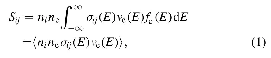
Figure 1.The calibrated iodine cell spectrum near the Ar ion LIF scheme.
With atomic spectra, the iodine spectrum is commonly used for accurate wavelength determination.Iodine lines can be weak at some wavelengths which can be an issue with small power lasers[37],which requires either a custom iodine cell at higher vapor pressure[61]or by heating the iodine cell.In addition, not all the lines are accurately covered by the standard reference table of iodine peaks [62], driving the demand to obtain custom calibration by measuring the wavelength of the iodine peak with a wavemeter [7, 31, 37].One way to accurately determine the zero-Doppler shift excitation wavelength is to send a laser in both forward and backward directions of the diagnosed volume and compare the resultant fluorescence spectrum, this eliminates potential particle drift within the diagnosed volume [61, 63].Alternatively, optogalvanic cells are also used to obtain absolute wavelength calibration, and they are often better than iodine in the sense that an optogalvanic cell can give the exact same line as the target fluorescence line if one chose the same gas as the one being probed[16,17,64,65].However,by nature of the optogalvanic cell being a plasma source, there is also no guarantee that the ion VDF in the cell is free of any drift velocity, particularly when they are generally very small device without any form of confinement to ensure plasma uniformity.Using a well aligned mirror to perform double fluorescence with the optogalvanic cell may alleviate this issue.
The wavelength sweeping of diode lasers is often considered to be linear with respect to the linear voltage ramp applied to the piezoelectric to control the Littrow angle, or otherwise the laser power supply’s synchronization signal of its frequency scan process.In practice, they are often quadratic-like [63].This facilitates the demand of additional calibration tools that give sharper and narrower peaks than the atomic spectrum to determine the exact wavelength more accurately.An Fabry–Perot(FP)etalon is a candidate of such supplement, as it can give extremely accurate wavelengths shifts.Figure 1 shows an example of laser wavelength detuning near the Ar II pump transition line at 668.6138 nm(in vacuum),the zero frequency detuning point is determined by the known iodine spectrum and rest of the frequency range is determined via fitting the etalon lines to an equal separation of 1.5 GHz, the specified free-spectral-range of the etalon [66].
3.3.Beam modulation
Modulating the laser beam is not always necessary, particularly when LIF is used to measure perturbation effects when signal is demodulated from the perturbation itself [39, 45].If a pulsed laser is used, no further modulation can possibly be used.However, modulating a CW laser enables signal recovery via lock-in amplification or FPGA up/down counting demodulation [67, 68], which can be important improvements to data quality as unprocessed LIF signal-tonoise ratio can be as low as 1/1000 or below.Modulations can be performed mechanically, electro-optically or acoustooptically, and we will briefly discuss each of these options.
Mechanical chopping is generally realized by an electronically controlled wheel blade,periodically blocks light via its slits.With ideal mechanical modulation, the laser beam should be much smaller than the slit, producing a squarewave like temporal variation.In this ideal situation,mechanical chopping enjoys the unique advantage of true zero beam intensity as it mechanically blocks the beam.In practice, the rise and termination time of the beam in which the beam is only partially chopped depends on the ratio between the width of the slit and that of the beam or the diagnosed volume, whichever of the latter is narrower.In addition, mechanical chopping frequency is generally limited to below 100 kHz, typically less than 10 kHz, and even at 10 kHz mechanical choppers can be quite hazardous to operate as they often involve razor shape wheel fans spinning at considerable speeds.
The electro-optic modulators(EOM)are made of electrooptic crystals that its optical properties change upon an applied voltage, resulting in the change of an incident light beam, typically rotating its polarization state.These devices are also known as Pockels cells.Using a pair of polarizers before and after a Pockels cell,a laser beam can be modulated via periodically rotating its polarization parallel and perpendicular to the exiting polarizer.The transmission range of these devices thus depends on the quality of the laser beam and the polarizers.Since electro-optic effect is by nature electro-magnetical,these modulators can operate in very high bandwidths up to 100 MHz without posing any safety hazards.EOMs require a high AC voltage to drive the modulator crystal,and the voltage needed for an EOM to fully modulate a laser beam is known as the Hall-wave voltage,which depends on the EOM’s design and the laser wavelength.This necessitates the use of high-voltage amplifiers/power supplies (HVA)which adds cost to implement EOMs.Suppliers often offer HVAs to pair with their EOMs (e.g.Thorlabs sells HVAs at a similar cost of the EOM itself at~2700 USD as of 2020).
A similar modulation device is an acousto-optical modulator(AOM),which diffracts an incident laser beam when an acoustic signal is applied.AOMs can operate in similar bandwidths of EOMs, and are occasionally more cost competitive than EOMs, but with a smaller transmission range and do not completely terminate the non-diffracted beam.One should also note that AOMs do not terminate a beam but diffract it at a rather small angle.Therefore,unless an AOM is packaged to be used with optical fibers, it is important to sufficiently separate the two output beams from the AOM before it is injected into the diagnosed volume.This makes a combination of AOM and free space lasers difficult to operate in a limited space.AOMs also require RF drivers to operate,but AOM suppliers often offer them at much lower cost than HVAs.
3.4.Collection optics and optical sensors
Choosing the optimal collection optics has always been an issue for any researchers trying to adapt an LIF diagnostics.A CCD camera combined with a sheet-like beam is ideally suitable for planar measurements without the need to move the optics [69, 70], but they are also limited by their pulse trigger acquisition, and unless some forms of lock-in amplified CCD are becoming readily available [70], using a CCD will mean limited ability to perform modulated signal recovery.CCD acquisition also favors high-power dye lasers as spreading the beam into a sheet considerably reduces its beam power density.PMTs can avoid this problem as it takes data only at one spatial point and signal recovery like lock-in amplifications can be performed pre-data-acquisition.However, to perform measurements of more than a single spatial point, one must move the optics relative to the diagnosed volume, which indeed is a nuisance when alignment is an issue.Previous LIF studies using PMT often measure VDFs only on a single axis due to the difficulty of multi-axis alignment of a movable PMT [71, 72].Acquisition of 2D spatial distributions of IVDFs has been recently demonstrated using a 2D movable lens [73, 74].Alternatively, Huanget alhas made two-axis LIF velocity measurements by moving the diagnosed volume, e.g.a Hall thruster [17].
One way to facilitate optical alignment with a moving diagnosed volume is the adaption of a confocal optical assembly [75], focusing the laser beam and the collection optics to the diagnosed volume with a single objective lens.As the injection and collection optical paths are united, confocal LIF setups do not require the alignment of translatable collection optics to the laser’s path.With the injection and collection optics being the same physical device sharing a single optical path, the confocal solution also allows LIF diagnostics to be performed from a single point of optical access on a plasma device.This is particularly convenient for probing IVDFs in devices where optical access can be severely limited,like Hall thrusters,toroidal devices and nonaxial IVDFs in linear devices.However,the collection optics of confocal LIF is much more complicated than ‘conventional’LIF collection setup,optical path must be split behind the objective lens towards both the laser injection optics(usually a fiber optics collimator) and the collection optics.This is generally done by either adding a small mirror behind the objective lens for a laser beam to join the optical path of the collected light[76],or reflecting the collected light by 90°to the collection optics via a mirror with a small hole in the middle for the laser beam to go through.One can also choose a dichroic mirror of suitable transmission/reflection wavelengths in place of a conventional mirror to selectively transmit/reflect the laser light and the fluorescent light,separating their optical paths without the need to partially block the objective lens.Simple schematics of all three methods are shown in figure 2.In addition,with confocal LIF the collection optics always faces the direction of the laser beam, and therefore, the direction of the IVDF to be probed.This makes axial measurements in long linear devices particularly difficult to design, although it also enables the LIF diagnostics to be compatible with an enclosed magnet setup which seals any radial access to the device.Focusing both the laser beam and the collected light to a single diagnosed volume also greatly increases the local laser photon flux density of the diagnosed volume.With LIF schemes having very low cross-sections, like TALIF diagnostics of neutral hydrogen [57], confocal setup might be the only solution to ensure signal-to-noise ratio.However, with common singlephoton LIF, as with all the schemes described in this review,one must be careful that even low power laser beams can be focused to a very high-power density, causing power broadening and reducing the effective lifetime of metastable particles, the effects of which will be discussed in later sections.
With limited fluorescence rate per volume, efforts have been taken to maximize signal recovery via better collection optics.Apart from a narrow band optical filter to distinguish ambient light, maximizing the solid angle from which fluorescent light is obtained from the diagnosed volume, and balancing between spatial resolution and signal-to-noise ratio are other considerations.One extreme measure is to build very long and large radius lens tubes and then increase the spatial resolution via employing a long-focal length lens to focus the collected light to a very small iris.Luntet alhave achieved a spatial resolution of the order to 50 μm by using 5 m collecting lens tube [77], keeping the lens assembly stationary and moving the detector.On the other hand, Skiffet alhas employed a 25 cm lens on a 50 cm diameter device,but with the very weak signal of the perturbed IVDF they still relaxed the size of the diagnosed volume to the order of 1 cm3[68].Alternatively, the same group also employed a PMT array and a movable electrode to obtain a 2D spatial distribution [78].
3.5.Time resolved and perturbation measurements
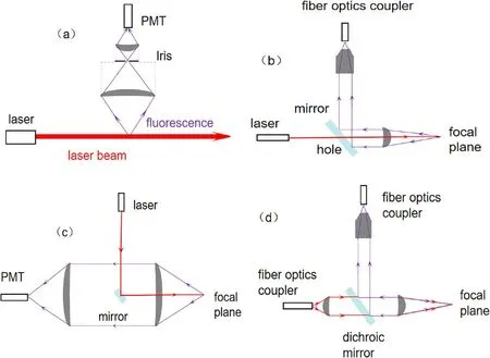
Figure 2.Schematics of(a)a conventional LIF optics setup,(b)and(c)confocal LIF optics setup with simple mirrors,and(d)confocal LIF optics setup with a dichroitic mirror.
Time-resolved LIF measurements are becoming increasingly common as people investigates deeper into perturbation phenomenon.‘Brutally’ increasing the modulation frequency and reducing the time constant of lock-in amplification well beyond the timescale of the temporal phenomenon provide the ability to perform synchronized measurements via a fast oscilloscope or post-acquisition signal processing, as demonstrated by Scimeet al[79] and Biloiuet al[80].Alternatively, it is also conceivable to first track the time evolution of the fast phenomenon via a sample-hold approach not unlike boxcar averaging, and then perform lock-in amplification via a much slower laser modulation [81, 82].Durotet alalso demonstrated a transfer function averaging technique via band-pass filtering, phase-sensitive detection and transfer function averaging[83].A pulsed laser,generally with a low repetition rate, can perform time-resolved measurements by phrase-locking the laser pulse trigger with the temporal phenomena if such phenomenon is repeatable [30].A similar procedure can be used with CW lasers via AOM modulation [40].For wave perturbations deliberately introduced into the plasma, one can also forgo laser modulation and perform lock-in amplification using the frequency and phase of the waves as the reference signal [39, 45].An alternative to this method is the Heterodyne-based method,which is to perform lock-in amplification on the mixed frequency of the laser modulation and the plasma perturbation,i.e.fM±nfDwherefMis the modulation frequency,fDis the plasma perturbation frequency andnis the order of perturbation [84].The Heterodyne-based method allows timeresolved measurements to be performed using existing setups that are generally already equipped with laser modulation and lock-in amplifiers, albeit with minor modifications.Eventually any attempts of time-resolved measurements are limited by the fluorescence frequency,which in turn is limited by the laser power,the metastable density and the diagnosed volume[28, 54, 85].
4.Resolving for the physical processes affecting LIF diagnostics
This section discusses physical effects that constitutes and affects the LIF diagnostics on IVDFs and NVDFs.As with any spectral measurement, line broadening is caused by several different mechanisms.We will discuss key effects including Doppler broadening, Zeeman broadening, power broadening, and isotope broadening.We will also introduce several key LIF schemes in low temperature plasma physics.
4.1.Doppler broadening
Doppler broadening is the fundamental mechanism that enables LIF diagnostics to measure VDFs.For a particle moving with a velocityvirelative to the lab frame, the frequency and wavelength of any photon emitted from the lab frame is Doppler shifted, which shifts the excitation laser wavelength for this particle in the rest frame.When the ion is traveling much slower than the speed of light, this frequency shift can be estimated by the first-order Doppler shift:
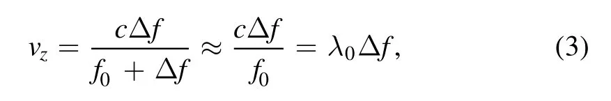
wherevzis the ion velocity,cis the speed of light, λ0the resonance wavelength,f0is the lab-frame resonance frequency, and Δfthe frequency shift (v–v0).The line width of the laser (~1 MHz) is much smaller than the expected Doppler shift for most room temperature ions(~1 GHz for argon).In an unmagnetized plasma of a gas with a single isotope,Doppler effect constitutes the only frequency shift fromf0,and transforming a detuned LIF spectrum via equation (3)directly provides the VDF.
4.2.Power broadening
While increasing the laser power increase fluorescent signal,there is a saturation limit to this effect, depending on the diagnosed particle density.It can be roughly understood as a case when all available particles in the diagnostic volume are exhausted by the laser excitation.This effect is far more evident in metastable particle LIF than in ground state particle TALIFs, since metastable particles often consist only of a small part of total particles due to the need to excite them from the ground state,and that single photon LIF has a much larger cross section than TALIFs.Increasing laser power beyond saturation broadens the resultant fluorescence spectrum due to the non-zero bandwidth of the laser, causing a broadened VDF measurement reflecting both the bandwidth of the laser and the Doppler broadening fromTi.This effect is far more evident with some of the dye laser setups with laser bandwidths of ~100 MHz [85, 86].However, even with~1 MHz bandwidth diode lasers,photons in the wings of the Lorentzian profile will begin depleting the metastable density when saturation is sufficiently severe.One should also note that tapered amplifiers (TA) become less stable at high gain,which can also contribute to a LIF spectrum broadening that seems like power broadening, but is a completely different effect.Other than directly comparing the measuredTiat different laser power, a simple way to reduce the power broadening effect is to operate the laser system at a spectral intensity below the saturation limit, which can be determined by increasing the laser power until the response of the measured LIF signal is no longer linear [87].
One should note that as discussed in the section 2, the total fluorescent rate, which decides the signal strength, is a matter of total laser power and total number of metastable ions or neutrals in the diagnosed volume.Therefore, power broadening, as with all metastable depletion effects, is an effect of the local laser power density of the diagnosed volume at which the collection optics is focused on.This means focusing a laser beam to a small volume will greatly increase the per volume photon flux in that volume, causing depletion of the local metastable density and power broadening.This can occur even if the laser power is low, and particularly affects confocal LIF setups where the laser beam is always focused.
Recent studies also revealed that metastable lifetime affects perturbation measurements [39, 45], this implies that increasing laser power, which reduces average metastable lifetime, also affects these measurements [88].This will be discussed in a later section.
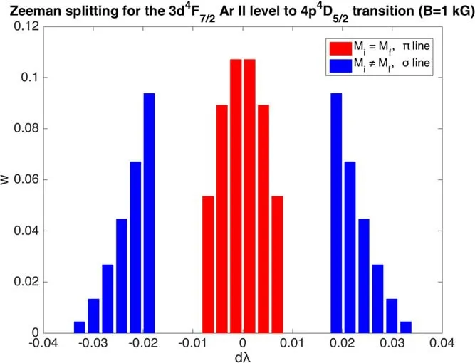
Figure 3.Zeeman splitting for the 3d4F7/2 Ar II level to 4p4D5/2 transitions (B=1 kG).
4.3.Line splitting and quantum effects
As with all excited emissions, LIF is affected by quantum effects splitting the energy states, a process known as line splitting.Common line splitting effects include Zeeman splitting, the splitting of degenerate states within a local magnetic field;hyperfine splitting and isotope splitting,which are the results of interactions between electron and the atomic nucleus.These effects are briefly discussed below.
4.3.1.Zeeman splitting.Most linear plasma devices, as with electric thrusters, can have considerable local magnetic field at the diagnosed volume.This causes Zeeman splitting of the energy state and therefore a broadening of the laser excitation frequency.Generally, the frequency shift of the Zeeman split states can be written as ΔvZ=εiv0Bwhere εiis the shift coefficient for each Zeeman component.In general, Zeeman splitting causes a degenerate transition to split into a group of π transitions and ±σ transitions.However, one should note that Zeeman effect is scheme dependent.For example, the 4s(21to 4p′(2)0Ar I pump line (excited by a 667.91 nm(in vacuum)laser)is split only into 3 transitions:a single π transition and two ±σ ones, but the 3d4F7/2to 4p4Ar II pump line splits into 18 transitions within a magnetic field: 6π ones and 12±σ ones [37].The relative strength of each Zeeman component can be evaluated using Wigner–Eckart theory [35], as shown in the figure 3.The spectral lines of π cluster are symmetrical near the central wavelength,while the two σ line clusters are asymmetric,and the most intense lines are closest to the central wavelength.
When the laser polarization axis is parallel to the axial magnetic field (perpendicular laser injection), only the π transitions are pumped.For parallel laser injection, σ transitions are pumped.±σ transitions can be separately excited via a quarter wavelength retarder inserted into the laser path to generate circularly polarized light.Note that while this can separate the Zeeman split transitions into ±σ and π groups to obtain a Zeeman shift (rather than broadening), the individual transitions within a group inevitably broaden the resultant spectrum.This necessitates advanced methods fitting the fluorescent spectrum with a convolved profile of the Zeeman lines and the particle VDFs[89].When the diagnosed particle VDF is a known function,like a Gaussian,the fitting process would be simpler.In even weakly collisional environments where charge-exchange and other effects deform the VDF into an unfamiliar form, this deconvolution process is expected to be a lot more difficult.
Recent experiments by Greenet aldemonstrated that using the symmetric nature of the Zeeman effect, one can measure the fluid velocity of an ion/neutral species without measuring the separate σ lines, but this only works if temperature and detailed VDF are of no interests for the particular investigation.
4.3.2.Hyperfine splitting.Hyperfine splitting comes from the interaction between the electron and the nuclear spin,it occurs only when the probed ion/neutral has a nucleus with a nonzero nuclear spin.This practically rules out all argon and helium ion and neutral LIF schemes (unless artificially produced isotopes like helium-3 are being probed).A number of xenon and krypton isotopes, however, do have non-zero nuclear spin which results in hyperfine splitting of the energy levels.
Without definitive experimental work resolving the hyperfine spectrum, past researchers tend to either simply accept hyperfine structure as a source of uncertainty [90], or adapt the most probable velocity as their result [91].While these measures are sufficient if one pursues only the drift velocity of the ions with limited accuracy, an accurate measurement of the ion temperature even for a Gaussian VDF depends on accurate deconvolution of the hyperfine and isotope splitting structure.In practice, charge exchange,ionization and recombination deform the diagnosed VDF into a non-Gaussian form, which complicates the deconvolution process as they do to the LIF spectrum convolved by Zeeman splitting.
4.3.3.Isotope splitting.Isotope splitting is the result of the minute mass difference of the nucleus.There are two effects behind isotope splitting: mass effect and volume effect [92].The mass effect is the result of nucleus motion,mainly related to light elements(Z<30).For heavy elements(Z>60),the volume effect is dominant.For medium weight elements like xenon, both effects contribute to isotope splitting.The mass effect usually consists of the normal mass shift and the specific mass shift.The normal mass shift represents the contribution of the reduced mass of electrons in the atomic system and the specific mass shift arises from the interaction between the external electron momentum.Simulation of specific mass transfer requires complex multi-body atomic structure calculation.Volume effect is usually modeled as the product of two factors.The first factor, called field shift, is proportional to the change in the total electron density at the nucleus as the atom undergoes an atomic transition.The second factor, called the nuclear parameter, represents the mean square change in the radius of nuclear charge between isotopes.As an example, figure 4 shows the naturally occurring xenon isotopic abundances and shifts of the 5d4D7/2to 6p4P5/2transition from Binghamet al[36] and Borghset al[93].There are nine stable isotopes of xenon,seven of which have natural abundances >1%, each causing an observably different transition energyEij, referred to as isotopic splitting.
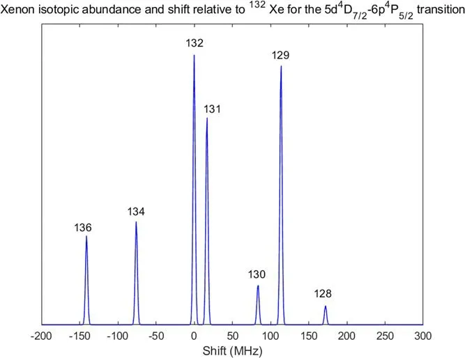
Figure 4.Xenon isotopic abundance and shift to 132Xe for the 5d4D7/2 to 6p4P5/2 transition.
4.3.4.Natural broadening and Stark effect.For every quantum transition there is a natural line broadening effect as a result of the Heisenberg’s uncertainty principle ΔtΔE>ħ/ 2,with the lifetime an electron energy state being Δt, this broadening can be approximated as Δ > ΔħEt./Typical LIF lines with excited states lifetime~10 ns give some 15 MHz linewidth from this broadening effect, corresponds to ~10 m s−1VDF broadening for most LIF schemes, which is negligible in most conceivable applications of plasma LIF diagnostics.
There also exist an electric field analog of Zeeman effect,known as Stark shifting.Stark shifting in almost all low temperature plasma applications is considered to be negligible for common LIF schemes [94].Stark effect becomes significant when one looks at the Rydberg states with highnclose to the ionization energy, which requires dedicated setups to pump a metastable twice to the Rydberg levels[95],and is beyond LIF for VDF measurements.
4.4.Extracting VDF from the LIF spectrum
In this section we will briefly discuss how particle VDFs and their associated key parameters can be extracted from the LIF spectrum.

Figure 5.An example of the detuning process with iodine and FP etalon signals: (a) determining Δf (t0 )=0from the iodine spectrum,(b) labeling FP etalon peaks by the number of FSRs the laser has swept past, (c) fitting for Δf (t) ,(d) detuned LIF spectrum.
4.4.1.Detuning the LIF spectrum.Raw LIF data generally come in form of signal versus time matrices.It is therefore important to accurately convert them into a matrix of signal versus the frequency shiftΔf.This consists of two processes:determining the point ofΔf(t0)=0when the laser wavelength matches the excitation line of the LIF scheme and determining the temporal sweeping rate to convert timetto their respectiveΔf.Both detuning processes require simultaneous acquisition of wavelength calibration data, as described in section 4.1.If an iodine spectrum with a known peak near the LIF excitation line is employed for absolute wavelength calibration,one can determineΔf(t0)=0byΔfbetween the iodine peak to the excitation line.Conversely, if one employs an optogalvanic cell with a mirror to obtain both the forward and backward VDFs of the particle via double laser fluorescence,Δ =f0 can be determined from the midpoint of the two VDFs.If multiple iodine spectrum peaks are present near the excitation line, it is possible to use an iodine spectrum alone to convert the time axis intoΔfby fitting for the respectiveΔf’s of these peaks relative to the excitation line.However, as mentioned in section 4.2, the accuracy and resolution of iodine atlas are often limited,reducing detuning accuracy.Thus, the use of an FP etalon is often preferred.FP etalons can give very accurate measurement of the relative change of laser frequency,producing a peak every time when a laser is swept past its free spectral range.To use the FP etalon to calibrate the relative change of the laser frequency, progressively mark each FP etalon peak asΔ = ×f nFSR wherenis thenth number of etalon peaks, then fit forΔf(t) to convert the time axis into frequency shift.An example of the detuning process is illustrated in figure 5.
4.4.2.Deconvolution of line splitting.To obtain the parameters from the VDF of the diagnosed particle species from the raw LIF spectrum,one must resolve the line splitting effects as described in previous sections, namely Zeeman splitting, hyperfine splitting and isotope splitting.All three mechanisms manifest in a similar way:they form a convolved spectrum combining their lineshapes with the other broadening effects to result in a broadened or split LIF spectrum.This can be mathematically written as
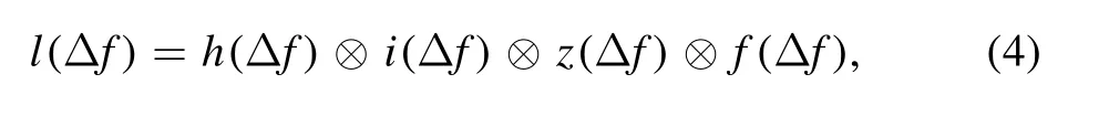
where Δl(f) and Δf(f) are the raw LIF spectrum and the VDF in frequency space, Δh,(f) Δi,( f) and Δz(f) are the convolution functions for the hyperfine split,the isotope split,and Zeeman split respectively.⊗is the convolution operator given bywhereCis the result ofAconvolved withB.A graphical representation of this process is shown in figure 6.One can see that with convolution functions for ideal line splits, which are summations of delta functions of the shifted lines at their respective frequency shifts and amplitudes, the operator essentially is a summation of the Δf(f)shifted to each of the split line and attenuated to the line’s relative amplitude.
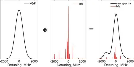
Figure 6.Graphical representation of a Gaussian VDF convolved with the hyperfine lineshape of the xenon 5d4D7/2 to 6p4P5/2 transition.
The deconvolution process is thus applying an inverse mathematical process of the convolution process,represent by the Ø symbol [96]:

In practice,this is essentially fitting the spectrum with the convolution functions for the deconvoluted spectrum.Common methods include simple inverse filter [97], rectangular inverse filter[97],Gaussian inverse filter [98,99]and wiener filter [100, 101].One would expect that the development of artificial intelligence may result in more accurate deconvolution processes,particularly if a mathematical form of the VDF can be reliably expected.
One should note that hyperfine splitting and isotope splitting are device independent effects.They only depend on the quantum effects resulted from the interaction between the electron and the nucleus of the diagnosed particle.Therefore,the convolution function of hyperfine and isotope splitting can be known independent of experimental conditions.However, Zeeman splitting depends on the local magnetic field of the diagnosed volume.Where experiments and theoretical calculations for Zeeman splitting for common LIF schemes can be well documented, one must acquire knowledge of the local magnetic field of the diagnosed volume to resolve for Zeeman splitting.Direct measurement of the magnetic field is sometimes difficult in diagnosed space inaccessible to Hall probes.Fortunately, via polarizing the laser into left- and right-hand polarized beams for laser insertion along the direction of the magnetic field to obtain two separate LIF spectra,one can calculate the magnetic field strength from the ±σ shifts, and therefore the convolution function of Zeeman splitting fairly accurately.4.4.3.VDF and parameters extraction.After detuning and resolving for the line split effects as described above,one can generally believe that the result LIF spectrum reflects the VDF of the diagnosed particles.Natural broadening and Stark effect, the electric field equivalent of Zeeman effect, do also convolve with the Doppler broadened spectrum, but they are negligible in most low temperature plasma devices for most LIF schemes.One can thus reliably obtain the VDF from the detuned and deconvoluted LIF spectrum simply by converting theΔfaxis to velocity using the first order Doppler shiftv=λ0Δf,provided thatv≪cwherecis the speed of light for most situation where LIF is applied.
For ions in the bulk or in collisionless situations, the VDF can be very well described by fitting a Gaussian distribution, given by:
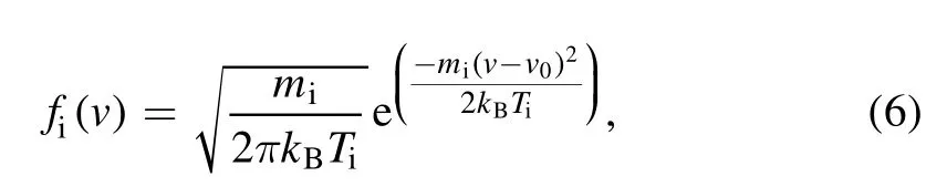
whereTiis the ion temperature,miis the ion mass,kBis the Boltzmann constant,andv0is the drift velocity.Realistically,VDF is deformed by charge exchange and ionization processes occur along any potential structures (sheaths,double layers, etc), causing the VDF to deviate from a Gaussian.It is thus of interest to obtain the exact VDF of the diagnosed particles.For any form of particle VDFs, the fluid velocity is defined by its first moment:
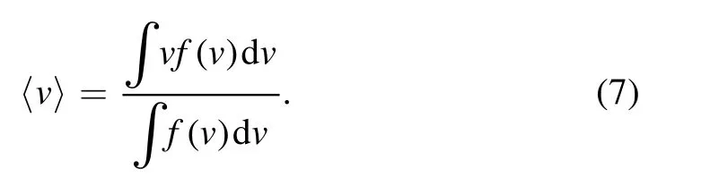
With non-Gaussian distributions, the physical meaning of temperature can be complicated, but an effective temperature can be defined bymi(〈v2〉−〈v〉2) ,where the second moment〈v2〉 is defined by:
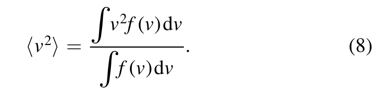
Note that the second moment is also associated with the average kinetic energyof a population of particles.For collisionless situations, calculating the change of〈v2〉 along a potential structure thus allows one to infer the change of local potential via the law of energy conservation:

And the electric fieldE= −dΦ(x)/dx.Collisions introduce loss of kinetic energy, although it might be accountable via introduction of mobility limitation into the fluid equations,but this requires precise knowledge of the collisionality of the diagnosed plasma which often defeats the purpose of employing LIF measurements in the first place.For cases where the neutral environment is weakly collisional, it is conceivable that one can fit for the forward half of the Gaussian distribution, being unaffected by charge-exchange collisions.This estimation ignores any possible thermalization effects between the non-Gaussian tail of the VDF and the Gaussian portion of the VDF,as well as ion-neutral scattering collisions.Another method to indirectly infer the electric field is to use Boltzmann’s equation to extract the acceleration applied on the VDF via resolving for its spatial and velocity derivative [64,102–105].An advantage of using this method is that any collisional effect can be separately resolved,simplifying the computation process [102], but collisional effects still need to be estimated separately.In most cases inferring the electric field from the VDF gives an estimate of the electric field with limited accuracy, but it remains useful when the diagnosed volume is not accessible by an emissive probe.
Electric field can be directly measured via the Stark effect but as discussed previously,using the Stark effect to measure the local electric field requires specific LIF setups that are more complicated than the ones employed to purely measure particle VDFs.Due to the complexity of these setups, they might also be less accessible than LIF diagnostics dedicated for VDF measurements.
According to the collision-radiative model, LIF signal is proportional to the local metastable density, as discussed in previous sections.Thus, one can measure relative density distribution via the total signal strength given by the total integration of the whole LIF spectrum.With proper calibration via a reference measurement with a Langmuir probe,one may be able to estimate the absolute density distribution.This, however, comes with an important assumption that the electron energy distribution function (EEDF) and neutral collisionality do not change over the diagnosed space.Due to the complexity of the associated collision-radiative processes and the lack of optical diagnostics to resolve arbitrary EEDFs in general, accurate determination of absolute density via the metastable density probed by LIF alone (even provided that the excitation cross section and the local photon flux are well known) is impractical.The Langmuir probe remains a necessary component in absolute density measurements.
4.5.LIF schemes
In this section, popular LIF schemes for common noble gas plasmas will be discussed, listed in table 1.The discussion does not cover all available schemes and mostly serves to demonstrate past and recent development of LIF techniques.
4.5.1.Ar II and Ar I.Argon remains one of the most common gas in use in the plasma physics community,partly due to its low cost, it is also by far the lightest noble gas with a metastable ion state available for single photon LIF diagnostics, making it one of the most common candidates in a multi-ion-species kinetics related investigation [11–13,119].Before diode laser based LIF is popularized,a common LIF Ar II scheme was to excite the 3d′2G9/2→4p′2transition with a 611.66 nm(in vacuum)laser and receive the 461.08 nm fluorescence from the 4p′2→4s′2D5/2decay.The partial energy level diagram of the scheme is shown in figure 7.This had been an attractive scheme for a few reasons.First, common plasma sources including microwave-induced plasma[107],ohmic discharge[108],and thermionic filament discharge [109], produces adequate metastable ion densities to obtain good LIF signal.Second, the 611.66 nm (in vacuum) excitation wavelength is accessible with a relatively long-lived dye: rhodamine 6G.Finally, many photo-multiplier tubes have maximum sensitivity for wavelengths ranged between 400 and 500 nm [7].
With diode lasers the 611.66 nm (in vacuum) line is inaccessible due to the lack of a suitable diode.Severnet alexplored the feasibility of diode-laser based Ar II LIF diagnostics looking at a number of possible schemes, listed in table 1[7,120].There are three key concerns selecting the most suitable scheme: the excitation wavelength should be close to the standard wavelengths 660, 670 and 685 nm of commercially available diode lasers (schemes 2–4), the diagnosed metastable state should have an adequate density in most plasmas, and the wavelength of the emission line should be sufficiently different from that of the plasma background light.
After an in-depth exploration of schemes 2 and 3 in table 1, the investigation resulted in the first use of a Ar II quartet metastable state to initiate the metastable ion LIF process, excited by a 668.614 nm (in vacuum) laser for a 442.72 nm (in vacuum) fluorescence, the partial energy level diagram of which is shown in figure 7.This scheme is accessible by commercially available 670 nm lasers, and potentially provides better signal than the 611.66 nm (in vacuum)scheme as the 3d4F7/2quartet metastable state has a lower excitation energy (17.69 eV)than the 3d′2G9/2doublet state (19.12 eV), potentially leading to a higher density of 3d4F7/2metastables in a low temperature plasma [35].
Keeseeet alreported on an investigation using a single tunable laser to measure both neutral (Ar I) and ion (Ar II)VDFs.The author used scheme 2 for the Ar II lines and a Ar Iline excited by a 667.91 nm (in vacuum) photon, listed in table 1,the Grotrian diagram of the Ar I transition is shown in figure 8.This also enable them to perform He I LIF with the same diode laser via a scheme excited at 667.99 nm (in vacuum),described below[35].Kellyet al[106]performed a similar investigation using scheme 4 on table 1 for the Ar II line and scheme 1 on table 1 for the Ar I line, the Grotrian diagram of the Ar I line is shown in figure 8.For other Ar I lines, Thompson [38] interrogated the feasibility of using the 1s5metastable with the lowest excitation energy, which is reported to have a lifetime of tens of seconds [121].The 1s5state is pumped to the upper state 2p2at 696.7352 nm (in vacuum), 2p3at 706.9167 nm (in vacuum) and 2p4at 714.9012 nm (in vacuum), shown in table 1.The energies and transitions used in the measurements reported here are shown in figure 8.

Table 1.Summary of LIF schemes in Ar I, Ar II, Xe II, Kr II, He I and I II.
4.5.2.Xe II.Measuring ion velocity distribution functions(IVDFs)in xenon plasma discharges is of importance in a wide range of research endeavors including laser physics [122],electric propulsion including Hall-effect thrusters HETs [18],and plasma boundary physics,which includes a wide variety of plasma processing applications [53].Many Xe II LIF schemes are currently in use,but a previously popular Xe II scheme in the visible wavelength range was excited by a 605.1 nm (in air)photon, shown in figure 9 as scheme 1.This scheme was common due to its accessibility via a dye laser.As diode lasers become a viable alternative to dye lasers, researchers will need to find other schemes as the 605.1 nm (in air) wavelength is inaccessible to the diode laser [18, 51].For this purpose, a 5d2F7/2→6p2D05/2→6s2P2/3excited via an 834.7 nm(in air)laser for a 541.9 nm (in air) fluorescence was developed[19, 113, 114], the Xe II scheme 2 shown in figure 9.Later a visible scheme for Xe II LIF exciting the(3P1)5d[3]7/2→(3P1)6p[2]05/2at 680.57 nm (in air) for a 492.1 nm (in air) fluorescence from the transition(3P1)6p[2]05/2→(3P1)6s[1]3/2is developed [31].The Grotrian diagram of this transition is shown in figure 9,the Xe II scheme 3.This scheme has a major spontaneous emission transition[32], and relies on a significant population at (3P1)5d[3]7/2(~13.4 eV from ground state Xe+)in the ion metastable state to generate the fluorescent signal.The 834.7 nm (in air) scheme has the advantage of having a tapered amplifier available near the wavelength, enabling higher laser power up to the order of 100 mW, while the 680.57 nm scheme takes advantage of the widely commercially available diode lasers near 680 nm, and facilitates safer operation as the laser dot is visible.
4.5.3.Kr II.In the thruster community,krypton is considered to be a potentially cost-effective propellant compared to xenon.
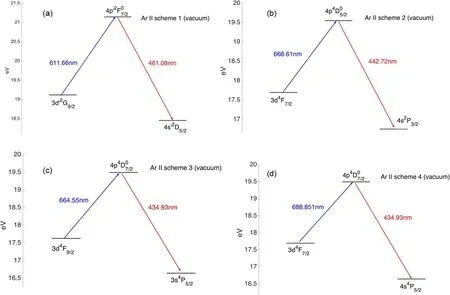
Figure 7.A partial Grotrian diagram for singly ionized Ar, depicting the LIF schemes 1–4 in table 1 about Ar II.
Harguset alpublished some excellent work on Kr II LIF measurements in the plume of a 200 W laboratory BHT-200-X3 Hall effect thruster with a diode laser [19].For Kr IILIF scheme[32],one can excite the 4d4D7/2→5p4D05/2transition with a 728.98 nm (in air) wavelength laser to obtain a 473.90 nm (in air) fluorescence from the transition from the 5s4P5/2state to the ion ground state,shown in figure 10.This scheme,and potentially Kr II LIF in generally, is complicated by its significant isotope shifts and hyperfine splitting of an odd isotope (83Kr36).As shown in figure 11, six known isotopes have significant composition in natural krypton gas, each producing an isotope shift of the 728.98 nm line.These isotope-shifted lines combine with the Doppler broadening from the IVDF to produce a complex convoluted spectrum.The quantum physics of the energy levels involved in the excitation transition has been well described by Harguset al[115].One of the key features of deconvolution is the ratio of thermal Doppler broadening and isotope shift between the most common isotope in the center (84Kr36) and its satellite line.With ion temperature exceeding 5000 K (2.3 GHz FWHM Doppler broadening) in Hall thruster environments, Doppler broadening of the IVDF becomes the dominant effect and the errors from the isotope shifts are more easily corrected.
In plasmas like multi-dipole filament discharge where ion temperature is in the order of room temperature, as investigated in Severn’s study [32], isotope shift becomes much more difficult to be accounted for.In these plasmas,the isotope shift broadened spectrum with a FWHM at 1.1 GHz,corresponds to the ion temperature of about 1100 K.By comparison, ion temperatures of argon and xenon discharges in these devices were consistently measured at 300–700 K[11, 32, 53, 111].This clearly indicates the influence of isotope shift related errors.For measurements in the bulk plasma, simply fitting the three most significant isotopes in the center(85%of naturally occurring krypton),gives a more accurate resultant IVDF, as shown in figure 12.However, in presheaths, sheaths and double layers, IVDFs often lack an expected shape due to complex collisional effects, which in turn produces complex convoluted spectrum beyond current deconvolution techniques.
4.5.4.He I.He I LIF intensity can be used to measure plasma density and neutral density distribution.In addition,neutral helium LIF can be used to study ion heating and plasma rotation in helical plasma sources.Two neutral helium LIF schemes have been investigated by Boivinet al[35].A common feature of these schemes is that they involve four different energy levels, such that an excitation transfer process (electron-induced collision excitation transfer)between the excited levels is necessary.In many ways, the He I diode LIF scheme used here is similar to the He I dye laser LIF scheme used previously [116].One of these schemes excites the 23Pstate via a 587.6 nm dye laser to the 33Dlevel.Then, a fraction of the excited ions undergo collision transfer excitation or an allowed IR transitions (18 620 nm)[123]to the adjacent 33Plevels,decaying to the 23Smetastable state with a 388.9 nm (in air) emission.The transition from 33Pto 23Shas a uniform branch ratio, shown in figure 13(a) as He I scheme 1.Another scheme, shown in figure 13(b)as He I scheme 2,uses a 667.8 nm laser to excite the(31Dto 31P)transition,after which an ion has to undergo similar collision transfer excitation process to reach the 31Pbefore decaying to the 31Dstate with a 501.6 nm (in air)fluorescence [117].Note that the rates of these excitation transfer processes are complex functions of plasma density and electron temperature [124].
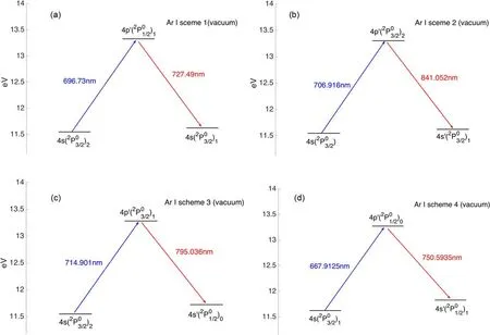
Figure 8.Energy level diagram for Ar I showing energy levels and depicting the LIF schemes 1–4 in table 1 about Ar I.
4.5.5.Iodine II.Steinberger and Scime [118] provided the first measurement of single ionized iodine (I II) fluorescence using the LIF scheme proposed by Harguset al[33].Because of the 5/2 nuclear spin of iodine, the absorption transitions used include obvious Hyperfine Structures.Based on their measurements, the first estimates of the magnetic dipole coefficients for lower (5D04) and higher (5P3) states were provided.The absolute wavelength values they measured in vacuum extend the accuracy of the values reported in the literature [125].
The I II scheme presented here was first investigated by Harguset alusing emission spectroscopy [33].The metastablestate is excited to the 5P3state by absorption of a 696.0694±0.0002 nm photon (in air).The upper state relaxes to thestate via fluorescence at 516.264±0.001 nm (in air) shown in figure 14 [126].
5.LIF application
5.1.Sheath/pre-sheath formation and basic plasma processes
The study on collisional deformation of the IVDF along the presheath,as depicted in the introduction,has sparked a series of sheath/presheath formation studies that spanned from single ion species [127], to two ion species [11–15], and finally to three ion species sheath/presheath formation.LIF enabled the first experimental test of the Bohm criterion via direct IVDF measurements, more than half a century after its theoretical formation [128] as well as Riemann’s weakly collisional presheath formation [129].LIF-enabled investigation on two ion species presheath formation[11, 52, 111, 127], presented the first test of Riemann’s multiple ion species generalized Bohm criterion [130] that eventually contributed to the experimental test of the instability enhanced collisional friction theory [131, 132],which predicts that, due to instability enhanced collisions,ions enter the sheath with similar velocities when ion concentrations are similar and that ions enter the sheath with their individual velocities when ion concentrations are very different.The theory is recently tested in three ion species plasmas and results show qualitative agreement [133], as shown in figure 15.The results are later shown relevant to the determination of ion concentration in low temperature plasmas [13], which in turn is relevant to the plasma processing industry.In various bounded plasma systems from plasma processing to tokamak region of scrape off layer, the assumption that that ions enters the sheath at their own Bohm speed remains common in applications of multi-ion species plasmas [134], despite being challenged by the results discussed above.The LIF diagnostics also enabled the first test of Chodura’s theory on magnetized presheath formation[135],and contested its prediction in collisional environments[73, 136].

Figure 9.Energy level diagram for Xe II showing energy levels and depicting the LIF schemes 1–3 about Xe II in table 1.
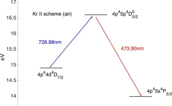
Figure 10.Energy level diagram for Kr II in table 1.
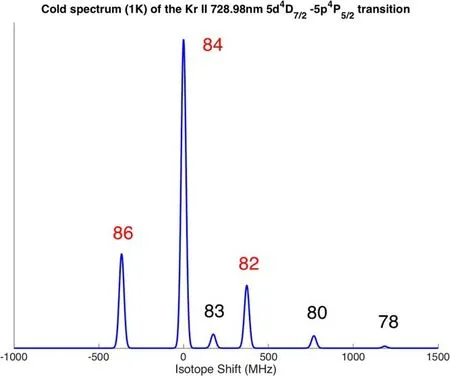
Figure 11.Krypton isotopic abundance and shift to Kr II for the 5d4D7/2 to 5p4P5/2 transition.
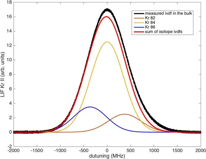
Figure 12.Kr II LIF signal in the bulk plasma consistent with an ion temperature of 1100 K, Doppler broadened FWHM 1.1 GHz,modeled by the simple sum of 3 Maxwellians.
There were also a significant amount of studies on fireball and electron sheath using LIF to investigate ion transport in these structures [137, 138], as well as plasma perturbation measurements measuring the perturbed IVDF [45, 68].
5.2.Helicon plasma related physics
More than half a century after the discovery of helicon waves[139, 140], helicon plasma sources remained an important field of study in plasma physics.Their almost unique properties of producing very high plasma density up to 1013cm−3,and electron temperature up to 10 eV [141] favor its application ranging from the study of planetary plasmas, to the recently popular study of wakefield accelerators[74,142]and to material processing applications [143].Extensive research has been done on the propagation and absorption of helicon wave [144].The high energy ion beam produced during magnetic field expansion of a helicon plasma into an expansion chamber has been of long-time interest,for their potential applications on space flight.This motivated investigations employing LIF and field energy analyzers(RFEA)to measure IVDFs in helicon devices and its plume [22–29].
Since the discovery of a double layer[145]structure near the helicon source’s exit in a diverging magnetic field[146, 147], it has been a question to the role of this double layer in forming the ion beam.Recently, Aguirreet alpresented [148] a high-resolution two-dimensional mapping of IVDFs via LIF measurements of an expanding spiral source,and found evidences for a new model in which the ion beam creation in the expanding plasma does not require a double layer.In these studies, LIF diagnostics can be limited by metastable quenching, as will be discussed below.On the other hand, RFEAs cannot be used to provide perpendicular IVDFs, and are not always reliable in measuring parallel IVDFs [23, 24].This necessitates the use of both diagnostics in these studies.
On the other hand,Siddiquiet alalso performed in depth investigation of ion dynamics in another kind of helicon double layer formed as a result of pressure balance when the helicon antenna is close to a boundary [136, 149].
5.3.Hall-effect thrusters
The fundamental parameters of a Hall-effect thruster are its thrust and specific impulse, both of which can be accurately inferred from the ion flow velocity which in turn is a parameter within the IVDF.LIF provided a means to non-invasively obtain the IVDF of a thruster plasma in the plume and even within the thruster where a retarded potential analyzer(RPA) or an RFEA is either inaccessible or significantly perturbs the local plasma.LIF also requires no prior knowledge of the local plasma potential to obtain an IVDF.
LIF technique had been used to measure the IVDFs of Xe+ions in the plasma of several Hall thrusters and in Hall thruster plumes [16–21].For instance, the far-field plasma characteristics of ion VDF and plasma ion temperature in 600 W magnetic shield and unshielded Hall thrusters are studied in [65, 150].An LIF optical bench along with the methodology is extensively described in[21].As explained in previous papers [90], the mean velocity approaches the theoretical limit in the plume near field, which means a large part of the applied potential is converted into ion axial motion.The IVDF of metastable Xe+ions was measured along the channel center line of the high-power PPSX000 Hall effect thruster by means of LIF [151], the LIF diagnostics reveal the existence of fast ions at the end of the acceleration region with kinetic energy above the supplied energy.Morever, LIF derived Hall effect thruster IVDF visualization was proposed by Hargus [152], both axial and radial velocities are sampled at a single cross section approximately 0.6 diameters downstream of the thruster exit.Huanget alhad also made two-axis LIF velocity measurements by moving the diagnosed volume [16].The IVDF of Hall-effect thrusters measured by LIF contains much more information than just the ion average velocity, as IVDFs generally reveal the physical processes ions have experienced before they are diagnosed.Lunaet al’s purpose was to extract as much information as possible from the IVDF[104],such as deducing the electric field and ionization frequency in the plasma directly from the LIF measurements.Time resolved LIF measurements were also employed to study breathing mode in Hall thrusters [81, 153].
Another important application of LIF in Hall-effect thruster related studies is the study of hollow cathode damages.Hollow cathodes serve as ionizers of the thruster plasma and neutralizers of the exhaust, but they are often quickly eroded by the ion flux which necessitates an orifice.Researchers had measured the ion energy distribution function in the hollow cathode plume [154] using a RPA and studies had shown that the energy far exceeds the discharge voltage (usually 15–20 V).This attracted attention on nonclassical ion transport, namely ion acoustic turbulence driven heating of ions[155–157],with direct measurement of IVDFs in the plume enabled via LIF and RFEAs [158–160].An example of LIF setup in the hollow cathode assembly is presented in figure 16 [160].
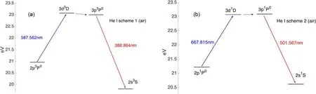
Figure 13.Energy level diagram for He I showing energy levels and depicting the LIF(a)scheme 1 and(b)scheme 2 about He I in table 1.
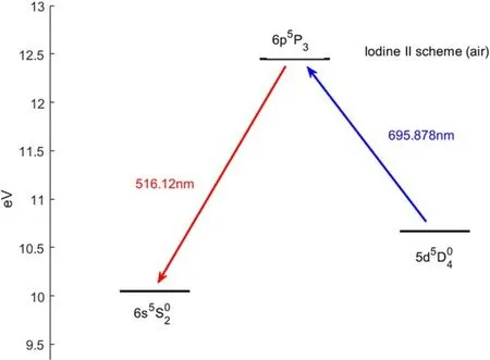
Figure 14.Energy level diagram for iodine II in table 1.
5.4.Plasma processing
With the extensive use of plasma processing in the fabrication of microelectronic devices [161], collimation and energy control of incident ions is becoming increasingly critical,especially in etching and deposition applications as processing precision increases.LIF provides a non-invasive plasma diagnostic to monitor bulk and presheath IVDFs[162].It can be used to monitor the 2D IVDF distribution via planar LIF with a sheet of laser light.LIF has been used to measure ion properties within DC and RF sheaths in ICP devices, as described by Mooreet alfor a dual frequency (2.2 and 19 MHz) RF sheath [30].Sadeghiet alalso reported direct measurement of the argon ions and neutral VDFs in an ICP[163, 164].LIF measurements of IVDFs of a pulsed inductively coupled plasma with have been reported by Jacobset al[165]with a two-dimensional flow pattern of the ion velocity above the substrate.Junet alhave also been measured metastable ion density and temperature by the diode LIF technique in magnetized inductively coupled plasma as a function of pressure, RF power, and magnetic field strength[166].The 2D ion velocity distribution of inductively coupled RF plasma had been measured with optical tomography via LIF in the bulk plasma and in the presheath of a plate with LIF and optical tomography,Zimmermanat alfound that ion temperature depends on RF frequency and is weakly dependent on pressure [167].
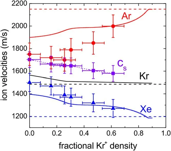
Figure 15.Ion velocities at the sheath edge for argon(red)and xenon(blue online) in plasmas of fixed mixture of argon and xenon gas with increasing injection of krypton. Te=1.95± 0.08 eV for all data points.The theoretical calculations assumed Te/Ti=75 and the density of argon and xenon ions being equal.Theory curves are given for all three ions in solid lines (krypton in black).Individual sound speeds are indicated by dashed lines.Reproduced from[133].@IOP Publishing Ltd.All rights researved.
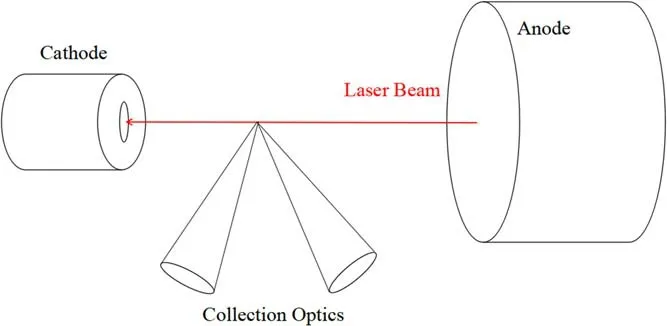
Figure 16.Laser-induced fluorescence system and the optical configuration of the cathode assembly.

Figure 17.(a) Ion acoustic wave electric field measured using LIF and the electric field probe at different frequencies excited by a grid.(b) LIF measurement of the wave electric field normalized by the probe measurements.Error bars stands for one-standard-deviation uncertainties.The theoretical prediction is plotted over the data.Reprinted (figure) with permission form [39], Copyright (2019) by the American Physical Society.
6.Future development of LIF in plasmas
6.1.Exploring the limitations of LIF in plasmas
While using LIF diagnostics in collisional environments,metastable quenching has always been of concern, as quenching significantly reduces LIF signal [28, 54].IVDF measurements via RFEA and LIF for an expanding helicon plasma by Gulbrandsenet al[23] and Harveyet al[24]resulted in an in-depth analysis and gave quenching cross section of metastables in an ion beam through the LEIA device.
Romadanovet al[40] attempted a time-resolved LIF measurements to study breathing mode in Hall thrusters and found that at the minimum of the discharge cycle, the LIF signal vanished while the current from the ion saturation probe remains.Where breathing mode is supposed to have a strong effect on electron temperature but not on ion density,a reduction of electron temperature implies weaker excitation of metastables,and the short residence time of ions is very short compared to the oscillation frequency, they can escape the diagnosed volume before being excited.
A key assumption in single-photon LIF is that metastable particles are in thermal equilibrium of non-metastable ones,and whether this is true has always been a question.Recently,Chuet alexamined the assumption in their study of the lifetime and history of metastable ion through wave-particle interaction [39, 42, 45].They found that for a metastable particle to represent other particles,their lifetime must be long enough for them to have experienced the same physical process with the IVDF in question.This gives a minimum frequency of the physical processes which LIF can probe, if the period of a particular physical process is longer than the lifetime of the metastable, the metastable would be quenched or fluoresced before they come to thermal equilibrium with the diagnosed IVDF.In Chuet al’s particular setup, this minimum frequency is approximately 10 kHz, with good agreement with a theoretical predictions, as shown in figure 17 [39].Note that any metastable ion or neutral’s lifetime depends on the particular metastable’s production and quenching rates, which are both LIF scheme and device dependent.In addition, increasing the laser power density,either by increasing laser power or by focusing the laser beam,will increase the excitation rate,which also reduces the average lifetime of metastables and causes perturbation measurements to fail,as the increased metastable burning rate exceeds the perturbation frequency.This had been demonstrated experimentally [88].
6.2.New LIF schemes:in search of more ion/neutral species to be measured
For more than 20 years, one of the key advances in LIF diagnostics is the exploration and perfection of new LIF schemes enabling diagnostics of different particle species.To this day,work resolving isotope broadening of Xe II and Kr II LIF is ongoing, and with noble gas plasmas, there still lacks experimentally proven LIF schemes for Ne II and He II ions.He II is of particular interest as it is the key impurity—helium ion in DT fusion plasmas.
Helium ion LIF for ITER helium density (nHe) and ion temperature(Ti)monitoring in the outer leg of its divertor had been proposed [168].It is an active diagnostic method to provide spatially resolved plasma parameters, which are important for the expected strong gradient along the flux surface.For this purpose,LIF scheme based on quenching the strongest line in the visible spectrum range of 468.6 nm
(transitionn=4→3) was proposed [41].Laser pumpedn=4→8 transition (485.9 nm) reduces the number ofn=4 particles and increases the number ofn=8 particles rapidly ionized by electrons (figure 18).
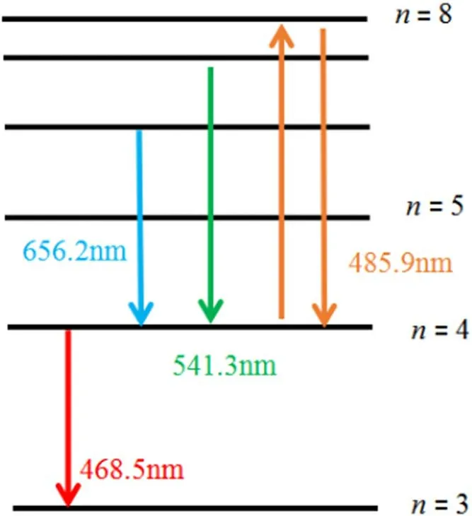
Figure 18.Spectroscopic schemes for LIF measurements of hydrogen-like ions of helium.
However,as of the date of submission He II LIF has yet been experimentally realized.This is because then=2 helium metastable ion has a transition energy of ~40.8 eV from its ground state.In most plasma devices, electron temperature is inadequate to produce such a significant amount of these electrons to populate the plasma with He II metastable ions.Plasma test bed to demonstrate He II LIF via applying of ECR heating in to a helicon source has been attempted, but laser excitation of He II fluorescence has yet been demonstrated [169].
6.3.Measurement techniques via novel laser topology
With past advancement of laser and optics technology, an emerging technique for plasma LIF diagnostics is the use of novel laser topology to allow VDF measurements perpendicular to the beam [170].Yoshimuraet alcomputationally evaluated the possibility to use LG mode optical vortex beam to measure ion or neutral Doppler shift azimuthal to the beam’s helical polarization.Their simulation work showed that the optical vortex beam can induce a Doppler effect in the azimuthal direction of the beam’s propagation,in additional to the longitudinal Doppler effect in conventional LIF diagnostics.If this technique is experimentally realized, it will be a powerful addition to existing LIF techniques,as it allows measurements of VDFs to be performed perpendicular to the beam’s direction,greatly expanding the accessibility of LIF diagnostics.On the other hand, the width of the helical beam is expected to span some ~10 μm [170] and spatial resolution of ~1 μm is expected for the collection optics to sufficiently resolve the fluorescence signal from various points of the beam,this would be a demanding requirement to the collection optics.
7.Conclusion
After more than four decades since its invention, plasma LIF diagnostic has seen significant advancement and is becoming increasingly common in the field of plasma physics for ion and neutral VDF measurements.They are seen from basic plasmas to thrusters, from helicon plasma to filament discharge, and is being developed towards their employment in tokamaks.Due to their non-perturbing nature,they are currently unchallenged in their ability to provide high resolution plasma ion or neutral IVDF in diagnosed volumes often inaccessible by probes and other means.As LIF techniques continue to develop and its physical limitations continue to be explored,they are expected to be increasingly common in all fields of plasma physics.
Acknowledgments
This work is supported by National Natural Science Foundation of China (No.11875285).
猜你喜欢
Plasma Science and Technology(2022年2期)2022-03-10
东坡赤壁诗词(2022年1期)2022-02-25
东坡赤壁诗词(2018年1期)2018-03-31
东坡赤壁诗词(2018年1期)2018-03-31
党员生活(2016年8期)2016-09-12
金融博览(2016年8期)2016-08-05
天津诗人(2014年3期)2014-11-14
文学界·原创版(2009年4期)2009-04-26
文学界·原创版(2009年4期)2009-04-26
文学界·原创版(2009年4期)2009-04-26
 Plasma Science and Technology2021年5期
- Plasma Science and Technology的其它文章
- Programmable electron density patterns induced by the interaction of an array laser and underdense plasma
- Study of the tungsten sputtering source suppression by wall conditionings in the EAST tokamak
- Explicit structure-preserving geometric particle-in-cell algorithm in curvilinear orthogonal coordinate systems and its applications to whole-device 6D kinetic simulations of tokamak physics
- Comparison between fluctuation of floating potential gradient and velocity of blob structure on HL-2A tokamak
- Magnetic diagnostics for magnetohydrodynamic instability research and the detection of locked modes in J-TEXT
- Dielectric breakdown properties of Al-air mixtures